Using Ariete, a pipeline’s Water Hammer Analysis can be extended beyond the simple outcome, for cases when the system under study requires water hammer control devices or procedures.
Ariete’s water hammer calculation can be complemented through the addition of control devices such as water surge tanks, surge relief valves and air chambers. In the case of analyzing pumping pipelines, it is even possible to include bypass lines around the pumping station to control the down surges generated at its discharge point when sudden power failure rundown occurs.
Creating the water pipeline’s Longitudinal Profile, as well as its upstream and downstream boundary devices, inserting water hammer control devices is as simple as locating the control point or chainage at which it will be connected and selecting from the list of available devices in the “Pipeline Interior Devices” dialog:
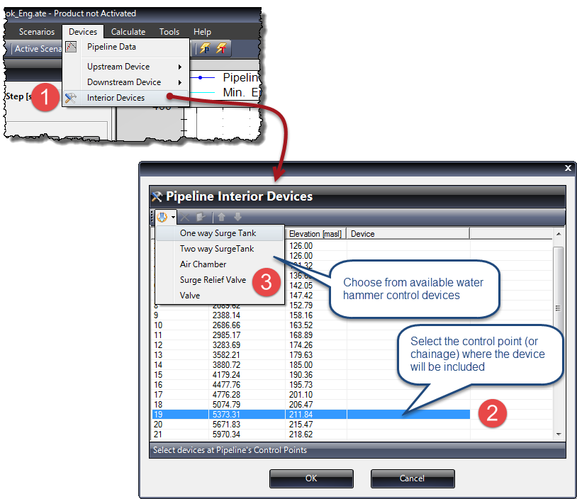
Then, according to the selected device, a dialog for entering the respective data will be shown. Let’s review each of the water hammer control device dialogs included in the current version of Ariete (Version 1.0):
One Way Surge Tank
The One Way Surge Tank is a storage tank (made up of a vertically placed pipe, most of the time) and is usually installed at the pipeline’s high points, having as its purpose the incorporation of the stored water towards the system when the pressure head in its connection point is less than the liquid height in the tank. Thus, down surge pressures, which could lead to water vaporization (cavitation) with subsequent column separation, are controlled.
The Surge Tank modeling in Ariete is accomplished by entering the geometric parameters indicated in the following dialog:
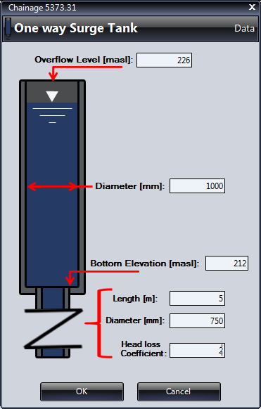
With these data, Ariete sets the surge tank initial water volume which will be used for the water hammer calculation.
Two Way Surge Tank (or Open-end surge tank)
This device, like the One Way Surge Tank, is a vertical pipe opened to the atmosphere, with the peculiarity that any pressure head fluctuation in its connection point with the pipeline causes flow to or from the tank. This allows it to moderate the pressure surges generated by water hammer occurrence.
Since the Two Way Surge Tank is supplied directly from the pipeline, it must be located on pipeline’s profile high points so as to cover, with the tank’s height, the hydraulic grade line elevation (at steady state conditions). This is a disadvantage that usually limits its usefulness, so quite tall and large tanks are required to accommodate large water hammer pressure fluctuations.
Modeling a Two Way Surge Tank in Ariete considers that it is a pipe interconnected to the pipeline at the selected control point, and for that you must supply the following data:
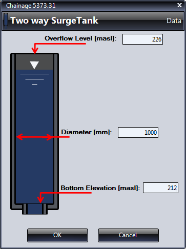
An important feature of the Two Way Surge Tank is that it becomes a very effective mechanism in the pipeline’s water hammer mitigation, as the closer to the source of transient disturbance it is placed, avoiding the transmission of pressure waves downstream of it.
Air Chamber (or hydro-pneumatic tank)
An Air Chamber is generally the alternative option to the use of Two Way Surge Tanks as, using the air’s compressibility property, this device avoids resorting to very high surge tanks which in most cases would be extremely expensive to build.
In essence, it is a (relatively) small pressurized vessel, containing both air and water, which is connected to the pipeline through a pipe with a differential discharge orifice (nozzle) which seeks to generate little resistance (low head loss) to the flow from the tank to the system but, in the case of flow incoming from the pipeline, it generates appreciable head losses with the consequent flow restriction. Thus, it becomes a damping device for high pressure surges, as well as a preventer of down surges and column separation — especially when located in the pumping station discharge pipe during power failure rundown.
Even so, in Ariete, it is possible to include Air Chambers in any pipeline’s interior control points.
The required parameters for modeling an Air Chamber in Ariete are presented in the respective dialog:
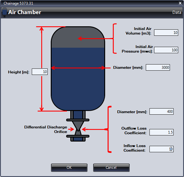
As shown, among the requested information are the initial (at simulation’s start time) volume and pressure of air in the vessel, so that Ariete can properly consider its effect on the pipeline’s water hammer calculation.
Likewise, to properly simulate the differential discharge orifice, it is important to consider the magnitude difference between the local loss coefficients for the outflow from the chamber and the one for flow into it, as well as the connecting pipe diameter.
Surge Relief Valve
A Surge Relief Valve is a device that, once the pressure head at its connection with the pipeline point exceeds a certain preset value, opens to discharge water to the atmosphere. Thus, the transformation of pressure energy (generated by water hammer in the system) into kinetic energy is achieved in order to provide relief from high pressure surges.
Thus, once you have selected the control point at which the surge relief valve is located, it only remains to enter in the Valve’s Data dialog: its diameter, local head loss coefficient, and the opening pressure:
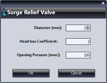
Note that, for the purposes of calculating the energy loss through the Relief Valve, it is assumed to be freely discharging at atmospheric pressure.
Inline Valve
The last possible device (although it is not exactly a water hammer control device) to place in the pipeline with Ariete is a control valve with the same diameter as the pipeline, which is intended to simulate devices like controlled-closure (or opening) valves as well as orifices (high local losses devices).
Thus, you must select among three types of control valves in Ariete: Gate, Butterfly or Needle valve, establishing, at each case, the local head loss coefficients according to the respective valve’s open percentages:

Water Hammer Control Devices in Pumping Stations
For pumping stations, in the Pumping Station dialog→Devices tab, we’ll see that it is possible to directly include at this upstream boundary condition three devices: Surge Relief Valve, Air Chamber and Bypass line around the station:
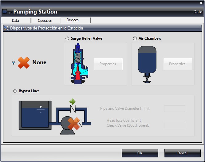
The required information for the first two aforementioned devices are already known from previous paragraphs, missing only highlight concerning the bypass line:
Bypass line around the Pumping Station
The bypass line consists of a pipe that connects the pumping station’s suction tank with the station’s discharge manifold, allowing only flow from the tank once the pressure head in the discharge manifold is below the water elevation in it. A check valve is installed in this bypass line.
With this device, it is possible to control the down surge pressures that occur after a pump stoppage (usually accidental), thus avoiding the appearance of negative pressures which could lead to cavitation and water column separation in the pipeline.
When this device is selected, it is only necessary to indicate the pipe and check valve diameter, further specifying the local loss coefficient in the valve when it is fully opened:

Visualizing Water Hammer Control Devices’ Results
Finally, it should be noted that, once the water hammer control devices are selected and the unsteady analysis is performed using Ariete, the specific results for each device can be viewed from the list inside the Charts and Tables button at Results panel. For example, in the case of a One Way Surge Tank, you will have the following options once the control point’s location is selected, from the pipeline’s profile view:

As shown, the water hammer calculation and analysis in pipelines, as well as the study of the effect of installing control devices using Ariete, is really handy. What do you think?


