

The CLOACAS (SEWERS) Sewer Pipes Editor, along with the required options provided to allow the user to define the geometry and required parameters for the hydraulic calculation of sewer pipes sections, includes several tools to streamline the sanitary sewer design work, as we shall see in this article.
The Sewer Pipes Editor is accessed through the properties of the selected pipe section, by either:
- Using the Properties tool in the DRAWING tab, Edit Panel;
- Selecting the Properties option that is included in the floating menu shown when you right-click the mouse button on the drawing area (with the sewer pipe selected); or
- From the Sewer Pipes table (main windows, tab Sewer Pipes) by double-clicking on the row associated with the pipe section to edit.
In the next image, the components of this Editor are highlighted:

1 Sewer Pipe Section’s Geometric and Hydraulic Parameters
In this area is shown, along with a sketch of the pipe’s profile, the necessary parameters for the geometrical definition of the sewer pipe section:

In this section, it is possible:
To set the actual pipe section as a Starting Sewer Pipe
A Starting Sewer Pipe is one on which the upstream manhole does not receive sewage flow from any other pipe section of the Sanitary Sewer network. This is an important aspect to create, among others, the project’s sub networks, as explained in this Tutorial.
To display the sewer pipe section’s hydraulic parameters
These values are updated automatically as changes to the sewer pipe section’s geometry are made from the dialog (changing invert elevations, for example). Thus, the design process performed by the user is easier, and it is not necessary to close the Editor in order to update those values.
To select the sewer pipe section’s Nominal Diameter (ND) and its length
Depending on the pipe section’s assigned Sewer Pipes Library (see point 3 below), the list of available diameters to be allocated (manually or by the automatic design function) will be shown.
Since the sewer pipes are created by drawing, picking its extreme vertices locations in the software´s drawing area, their lengths, by default, will be automatically calculated from the respective coordinates. But if you want to override this, you can activate the option “user defined Len”: to enable the text box at right and enter the pipe section’s length value.
To display the pipe section’s extreme manholes ground elevations
These fields will display (they are not editable from this dialog) the manhole’s ground elevation entered from the Manhole’s Properties dialog.
Display or set the pipe section’s upstream and downstream invert elevations
When the inverts of the sewer pipes converging to a certain manhole have the same elevation, the software will automatically set in this manhole the invert elevation, and it will assign its value to the converging sewer pipes inverts, blocking its manual modification from the Editor (unchecking the checkbox next to the inverts text boxes).
But when, for reasons such as the occurrence of “drops” among the manholes’ affluent and effluent sewer pipes, the invert elevations are different, you will have to resort to manually setting the pipe section’s inverts values (checking the checkbox next to the respective invert value).
Thus, when the checkbox next to any of the invert fields in the Sewer Pipes Editor is not checked, the manhole’s invert elevation will be automatically assigned to the respective sewer pipe’s endpoint. In this case, the text box with the invert value is not enabled, warning you that it cannot be changed manually.
If the check box is checked, the user will be able to enter the invert elevation value “decoupling” the manhole’s and the sewer pipe’s respective invert elevations. The following figure shows the two aforementioned situations:

[/su_note]
To visualize the Sewer Pipe Section’s Extreme Depths.
The difference between the ground and invert elevation will be displayed as the depth value at each end of the sewer pipe.
To set the Manning’s Formula Friction Factor
By default, the Manning’s coefficient used for sanitary sewer hydraulic calculations will be the one the user sets in the Sewer Pipes Library that has been assigned to the actual pipe section.
In case the user wishes to override the library’s friction factor and to enter a specific value for any particular sewer pipe section, it is mandatory to check the box next to the Manning Coefficient text box to allow editing of the current value.
To specify the Invert Elevation’s changing percentage
When the invert elevation’s manual change option is enabled (checking the box next to the respective text box) in any sewer pipe section, it is possible to change the actual elevation by directly entering its numerical value.
But it is also possible to use the elevation’s increase and decrease buttons at the right end of the inverts text boxes so as to, gradually, modify the values at intervals, for example, of one cm:

At the bottom, in the “Elevation Increment [%]” field, it is possible to set the value of the elevation interval.
Here the entered value is a percentage of the unit of measurement used for elevations (length units in the SETTINGS tab of the software); for example, if the current unit is meters, when specifying a value of 1%, the changing elevation interval will be 0.01 m, which is one cm:

2 Parameters for the Design Sewage Flows Calculation
Depending on the selected method for calculating the design sewage flow to be used in the Sanitary Network analysis and design (as seen here), in this area of the Sewer Pipes Editor the necessary input fields will be shown, so as to allow the user to specify the corresponding value for the actual pipe section.
3 Diameter and Bedding Class Definition
Options in this group allow you to select the Sewer Pipes Library (see this article) that will be used to define the actual pipe section’s diameter (manually, selecting from the respective list in the diameter field, or automatically, by the software, when the automatic design options are used).
At the bottom of this group we will see the Set Bedding Class Option. If this option is disabled (default condition), the sewer pipe section bedding class selection will be made automatically, based on the respective burial depths specified in the assigned Sewer Pipes Library.
If the user prefers to override the automatic selection option, he must check the Set Bedding Class checkbox in order to select, from the list, the bedding class to be used in the actual sewer pipe section:

4 Sewer Pipe Section’s Longitudinal Profile
When the ground slope between the extreme manholes of a sewer pipe section is not constant, it is convenient, both for adequate representation in the longitudinal profiles as well as to calculate the volumes of excavation and backfilling, to specify intermediate ground elevation points to allow a better definition of the topography in the sewer’s path.
The group Pipe Section Longitudinal Profile allows us to make this intermediate points specification in the section´s profile. You just need to click on the Insert New Row option at the right side of the table and assign the distance from the start of the current sewer pipe section (downstream manhole) to the point in question as well as its ground elevation:

Note that the start and end ground elevations of the sewer pipe’s profile will be controlled by the value of the ground elevation of the respective manholes as well as the pipe section’s length. They are not editable from the Pipe Section Longitudinal Profile group.
5 Sewer Pipe Section’s Designing Tools
Options at the bottom of the Sewer Pipes Editor allow us to perform “individual” changes, i.e., for the current pipe section and, depending on the selected option, perform changes in the downstream or upstream pipe sections in order to keep an overall design consistency.
Let’s study each of them separately:
Modify the Invert Elevations of every Pipe Section located Downstream of the Current Section
When this option’s associated button is clicked, a text box will be shown so as to enter a depth value (positive if you want to increase the pipe section’s depth or negative if you want to reduce it) which will alter the invert levels of the adjacent sewer pipes (upstream or downstream, depending on the selected button) within the same sub network to which the current sewer pipe section belongs.
For example, in the A1 Sub network, we show the output when using the invert elevations modification option for those pipe sections located downstream from the section A1.1-A1.2 in the Sewer Pipes Editor:

In this case, with the box next to the downstream invert elevation of the A1.1-A1.2 pipe section not checked (anclarrasantes as explained here), its slope has been also modified. If, before using the modification option, it was checked, you have the following output:

To Calculate the Current Sewer Pipe Section’s Required Longitudinal Slope
This option allows us, based on the sanitary system’s design parameters specified in the Project´s Settings, to determine the required longitudinal slope for the current pipe section. And, according to the selected button, it will also calculate the necessary invert upstream or downstream elevation, without modifying the opposite one, of course.
It is important to note that the calculated invert levels, as well as the longitudinal slope of pipe sections, are “ideal” values, based on the project´s design options. The Sanitary Sewer Design Software will search, depending on the accuracy of the elevations (two decimals, assuming it reaches one cm of accuracy, when the measurement unit is the meter, for example), the “real” longitudinal slope value to be assigned to the sewer pipe section (which depends on the invert levels). Of course, the found slope in any case will ensure the system’s design condition.
For example, the following image shows the sequence on which the longitudinal slope calculation option is selected in order to modify the upstream invert level of the pipe section:

So that the user decides whether or not to modify the current invert elevation values.
Match the Current Sewer Pipe Section Longitudinal Slope to the Contiguous Pipe Sections
When the designer deems it necessary to maintain, as far as possible, a constant longitudinal slope along a Sub Network, he can use this option, with which the software will determine the required invert elevation (upstream or downstream, depending on the selected button) to match the current sewer pipe section’s longitudinal slope with the one located at Upstream or Downstream longitudinal slope.
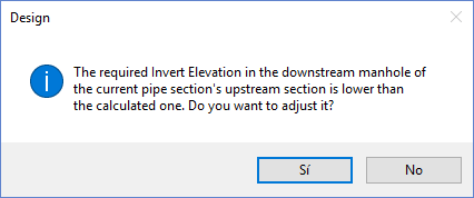
The following image shows the message presented to the user when this option is selected, in case it is desirable to match the current pipe section’s longitudinal slope to the value of its upstream one (modifying the downstream invert elevation):


In this case, it was found that the calculated invert elevation would block the discharge into the sewer pipe section located downstream of the current one (it is at a higher level), to which the user should answer “Yes” to equalize this invert value (the upstream invert value of the downstream pipe section) to the value calculated with this option.

To Change the Current Sewer Pipe Section’s Invert Elevation according to the downstream invert elevation in its Affluent Pipe Sections
Sometimes, when the automatic design of the sewer pipes networks is performed, will be found that exists tributaries that have a lower invert elevation than the receiving pipe section, which establishes that the water cannot be conveyed by gravity through the sewers network.
In our Sanitary Sewer Design Software, the user is warned about this situation when the automatic design options (at the SEWER PIPES tab, Calculation and Design panel) are used:

And, if we review the Longitudinal Profile, we will find situations like this:

We see, in our example, that the A4 Sub Network discharges at a higher elevation in the A4 manhole, which ensures continuity in the sewage water collection. But with the A5 Sub Network, this is not the case because it is discharging at lower levels, which would result in the inability to receive and convey the associated flow.
To overcome such situations, the option of modifying the invert elevations of the pipe sections located downstream of the current section’s tributary sub network has been incorporated.
In the above case, we edit the A4-A5 pipe section and select the option, as outlined below:

Pressing “Yes” in the last warning dialog and closing the Sewer Pipes Editor, we see that now the A0 sub network’s longitudinal profile is consistent with the affluent collector at A5:

Thus, as we see, the specific design of sewer pipe sections, without losing sight of what actually happens with the rest of the sub network of which they are part, is simplified by using the options available in the Sewer Pipes Editor.