

In CLOACAS (SEWERS), our Sanitary Sewer Design Software, a dialog has been included which allows the creation of different pipe libraries and which will keep the hydraulic as well as the constructive and cost properties of the sewer pipes of your choice. This article presents the characteristics of the Sewer Pipes Libraries Manager.
Most often, sanitary drainage systems are made up of sewer pipes of the same material, usually concrete, but with different “classes” and with each of them associated with the pipe’s ability to withstand external loads at various depths.
Similarly, there are numerous sewer pipe bedding classes, each with a specific carrying capacity (or load factor), which also will contribute to a certain pipe class to withstand (or not) greater external loads.
Based on the aforementioned considerations, the different fields available in the Sewer Pipes Libraries Manager have been set, and this dialog can be accessed from the SETTINGS tab → Calculation Parameters panel → Pipes button:

From this dialog it is possible to:
1. Create, Delete, and Update Changes made to the current sewer pipes library.

2. Set the Name and Description of the current sewer pipes library and create a new library by copying an existing one.
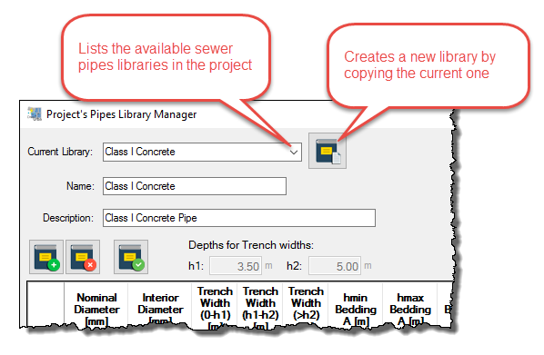
3. Set the sewer pipes’ geometrical and hydraulic properties.
For each pipes library, it is possible to specify a range of diameters so that our Sanitary Sewer Design Software is able to select, when the automatic design options are used, the one that meets the project´s design hydraulic conditions. The internal diameter will be used in hydraulic calculations, together with the Manning’s Friction Coefficient. The nominal diameter will be used to “name” the size of the sewer pipe in the results tables.
It is important to note that in the automatic design of the pipe sections in the sanitary drainage system, specifically in determining the sewer pipe´s diameter, the software will take as maximum available diameter the highest value that the user has specified in the library assigned to the respective pipe section, whether or not this diameter satisfies the design conditions (hydraulic capacity, full flow velocity, etc.).
It is therefore recommended to be aware of the messages that the software will generate, for example, changing the color of the value in the field Qr/Qc in the sewer pipes table at the main window (SEWER PIPES tab).
4. Define, for each sewer pipe diameter, the trench widths to be used in the calculation of excavation and backfilling volumes.
“Trench Width” columns are intended to offer three different excavation widths, depending on the maximum depth that the software detects at each sewer pipe section, once the sanitary drainage system is designed.
Thus, having specified the heights h1 and h2 in the Excavation and Materials Parameters Settings dialog, which is accessed from the Quantities button, Calculation Parameters panel of the Settings tab:

we will see that, in the Sewer Pipes Libraries Manager, these values appear (and cannot be modified from here):

5. Specify, for each sewer pipe diameter, the permissible depths for three types of bedding classes, so that the program automatically set the required bedding in the automatic design.
By default, our Sanitary Sewer Design Software allows us to use three types of bedding classes:
- Type ‘A’ Bedding. This is the one with a greater bearing capacity, generally formed by a concrete bed on which the sewer pipe rests.
- Type ‘B’ Bedding. This offers an intermediate load capacity, consisting of a granular bedding.
- Type ‘C’ Bedding. This is the one with the lowest capacity, considering that the placement of the pipe is directly over the excavated soil.
The following image shows these pipe bedding types:

It is to be noted that in the software, at no time are calculations of load capacity of the pipe made when combined with any of the referred bedding classes. In fact, the dimensions that must be specified in the Pipe Beddings tab, at the Excavation and Materials Parameters Settings dialog, are used only for the purpose of determining the respective quantities of work (excavation and backfilling).
It is therefore important that the user has information, usually provided by sewer pipes manufacturers, about the maximum allowable burial depths to use when similar to those bedding classes included here are used with their pipes.
Thus, with the sewer pipe’s load capacity data to be specified in the current library, it is necessary to define the minimum and maximum depth values in each pair of columns, for each bedding class:

An important aspect added to this dialog is the possibility of setting the bedding class selection criteria using the software’s automatic design option. As can be seen in the Bedding Class Selection Priority box (above image), you have two options:
- A – C: States that, according to the minimum and maximum depths resulting in any particular sewer pipe section and, of course, depending on the assigned diameter and pipe library, the software will first check the column for Type ‘A’ bedding class. In case the design’s depths are within its depth’s range, this will be the selected bedding; otherwise, the values for Type ‘B’ will be checked and so on until the Type ‘C’ values, in order to set the final pipe section’s bedding class.
- C – A: This is the inverse approach to the previous case. The software will start the bedding class selection based on the depths values of the Type ‘C’ bedding class and, in case it is not possible to use it, it will then move to type ‘B’ and, finally, to type ‘A.’ This is our Sanitary Sewer Design Software default option, which is, of course, the one that generates the lower cost solution, if applicable.

In the hydraulic design of this sewer pipe section, the software detected a minimum depth of 1.50 m and a maximum of 1.80 m. When the A-C priority option is checked, the program will select the bedding class ‘A’ for the pipe because, for its diameter, it could be placed at depths between 0.8 and 4.90 m. Both values “cover” the actual depths of the pipe section.
Now, using the C-A priority option, the software will select the bedding class ‘B’ for this sewer pipe section because, when reviewing the minimum and maximum depths for type ‘C’ (first searching option in this case), it is found that the minimum depth is admissible (1,45 m < 1.50 m), but its maximum (1,80 m > 1.75 m) is not.
6. Set, for each diameter, the Sewer Pipe Unit Cost (per length).
For the purpose of calculating the total cost of supply and installation of sewer pipes in the sanitary drainage system’s project, you can define its cost per unit of length.
It is important to note that this unit cost will not be modified by the software in the event that, when initially introduced, it was associated with one unit of length (meters, for example) and then the user changes to another unit (feet, for example). In situations like this, you must make the change manually in order to obtain consistent results.