The Ariete software’s approach toward Water Pipeline Design (either supplied by gravity flow or by pumping) focuses on visualizing, at its Main Interface, the Maximum Allowable Hydraulic Grade (or Piezometric Head) Envelope that the pipe is able to withstand based on its mechanical properties, i.e. according to its Nominal Pressure (NP) or pressure rating.
The fundamental aspect in Water Pipeline Design regarding internal pressure is to guarantee that, under all “regular” operational situations, the Nominal Pressure of the pipe exceeds the system’s operating or internal pressure, so as not to exceed pipe’s mechanical resistance and not run the risk of pipeline failure.
The criterion of Water Pipeline Design for Internal Pressures is applied in Ariete for two possible conditions, simultaneously, if desired by the user:
- Creating the Envelope of Maximum Allowable Hydraulic Grade that pipes can withstand under steady flow conditions.
- Creating the Envelope of Maximum Allowable Hydraulic Grade that pipes can withstand under unsteady flow conditions.
The fundamental difference among these two conditions is that it is assumed that steady flow conditions are those to which the water pipeline will normally be subjected during its operational life, thus requiring a more conservative level in terms of the Nominal Pressure to be used in the Design (i.e. always guarantee that pipes’ Nominal Pressure exceeds the working pressure).
In the case of the unsteady flow conditions, i.e. when water hammer occurs in the pipeline, it is accepted that it is a situation which, if observed, will happen eventually and for a very short time span, at some moment along the pipeline’s operational life, in which case, and always at the discretion of the Designing Engineer, it would be possible to be less conservative in terms of the Nominal Pressure used for the water pipeline design.
As we highlighted in the previous paragraph, using the given criteria for the unsteady flow conditions, it will depend on the good judgment of the water pipeline Designing Engineer, always taking into account the specific characteristics of each system under analysis.
It may even be the case that the design codes or standards in each country establish the safety factors to consider in each case which, of course, cannot be ignored in your water pipeline design.
Actually, no two Nominal Pressures for each kind of piping exists, as could be understood from the previously given conditions, as its denomination, regarding the Maximum Internal withstood pressure, is unique (PN 6, 125 Class, Sch. 40, K8, etc. depending of the standard under which pipes are manufactured). But what is possible is to consider that, under unsteady conditions, pipeline components (pipes, valves, etc.) will be able to withstand pressures above their Nominal Pressures, with the understanding that those conditions will not happen frequently.
One option is to suppose that the Pipe’s Maximum Allowable Pressure, always speaking of unsteady flow conditions, is equal to its test pressure, which could be up to two times the manufactured Rated Nominal Pressure.
For example, for a cast iron pipe, with a nominal diameter of 800 mm and K7 (ISO standards) pressure class, we could talk about two allowable pressures for Water Pipeline Design:
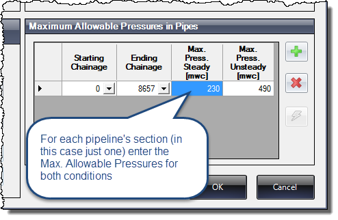
- The Nominal Pressure for the Normal Operation case (steady flow condition): 23 bar (or 230 meters of water column), as Maximum Allowable Operating Pressure (rating pressure), according to the manufacturing standards (ISO in our example).
- The Pipe’s Minimum Test Pressure (unsteady flow condition): 49 bar (or 490 meters of water column). This is the pressure that the manufacturer states in its factory’s tests for piping components, for each pressure class, and which is referenced in the respective technical catalogs.
In cases such as this, it is important that the Designing Engineer note that, in the case of the Maximum Allowable Pressure for Unsteady Conditions, the selected value must not exceed the maximum pressure at which the pipe is tested in place (once it is installed) and which can be from 1.25 to 1.5 times the Nominal Pressure.
Creating the Pipeline’s Maximum Allowable Piezometric Heads in Ariete
Having thus defined the criteria used by Ariete for the Internal Pressures in the Water Pipeline Design, let’s see how to define the necessary values to plot the respective envelopes for our pipelines’ projects:
By pressing the Edit Pipeline button from Ariete’s Devices toolbar:
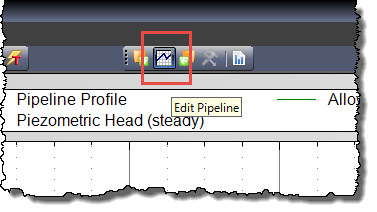
you have access to the Pipeline Data Dialog:
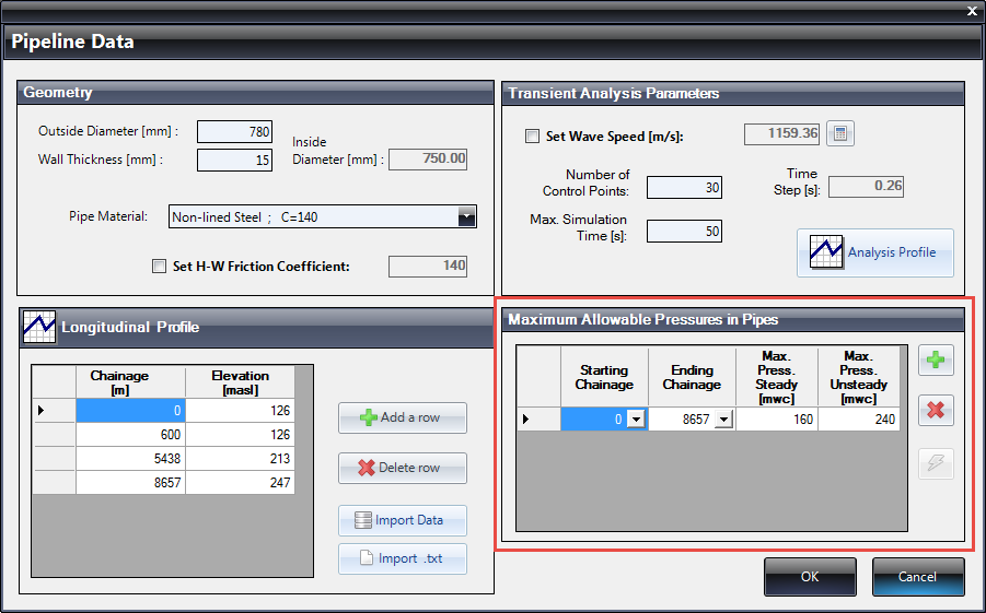
Where you will see, in the lower right box, a table where we can specify, for each pipeline’s analysis section (defined by two consecutive Control Points), the Maximum Allowable Pressures for steady and unsteady conditions that pipes can withstand based on what we have previously seen here.
Thus, if we refer to the example of the K7 (ISO) class pipe, and consider that the same pressure class is used across the pipeline’s total length, we would have a view similar to the following:
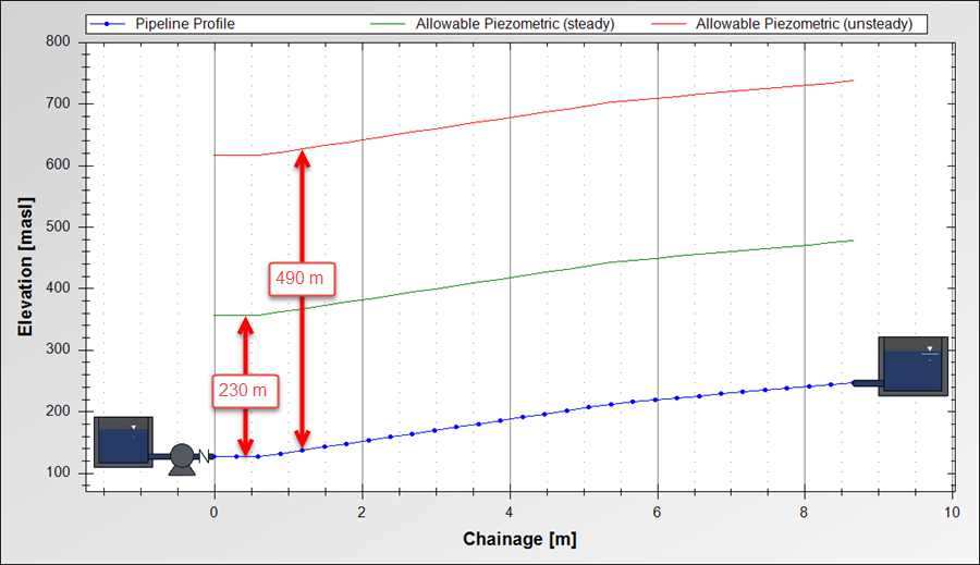
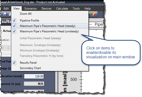
Thus, when closing the dialog and returning to the Ariete’s Main Window, the Hydraulic Grade Envelopes are shown for each condition:
With the design envelopes defined, you can now start the process of Pipeline Design and Analysis with Ariete. For example, if we analyze the steady flow condition (click on Calculate → Steady State), the piezometric head generated for this condition will be shown in the pipeline’s longitudinal profile, from which we can establish the pipeline’s adequacy (or not) to withstand internal pressures under ‘normal operation’ by visual comparison:
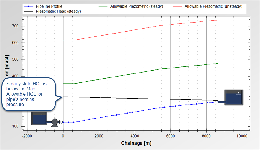
We see that the Pipe’s Nominal Pressure is enough to withstand the internal pressures to which the system is subjected at Normal operating conditions, as its respective piezometric envelope (in black color on above image) is located below the maximum allowable one (green color).
Now, when performing the analysis for Water Hammer occurrence conditions – pump’s power failure (unsteady flow) — we obtain the following results:
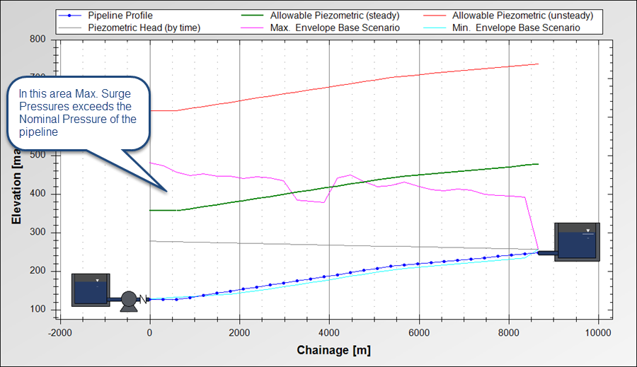
Here we see that the envelope of the Water Hammer Maximum piezometric head is above the Maximum Allowable one for steady flow condition (pipe’s Nominal Pressure), even when placed at once under the Maximum Allowable Envelope considering unsteady Condition (related to a lower safety factor).
Here is where the Designing Engineer’s Criterion and the regulatory restrictions on Water Pipeline Design come into play, to establish if it is acceptable that water hammer pressures are resisted on the compromised section (upstream of chainage 3000 m in our example), counting the fact that the pipes can withstand higher pressures than the nominal ones, or if it requires a specific solution (water hammer control devices installation).
A Solution (quite conservative) Possible in the Water Pipeline Design: To increase the Pipe’s Nominal Pressure
Even when, in our opinion, the aforementioned system example will properly operate in both studied situations (steady flow and water hammer occurrence), we now propose a conservative solution which would be to consider that the pipe withstands the maximum surge pressures only with its Nominal Pressure.
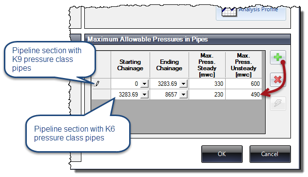
In this case, the proposal would be to use a higher pipe pressure class (K9) for the first 3300 m of pipeline section in which the Water Hammer pressures exceeds the Nominal Pressure of a K6 class pipe. For K9 class, the nominal pressure is 33 bar while its test pressure is 60 bar.
To make this modification, we’ll return to the Pipeline Data Dialog to add a row (pipeline section) in the Maximum Allowable Pressures table:
after which, when closing the dialog and returning to main window to perform a new unsteady run in Ariete, the following results will be obtained:
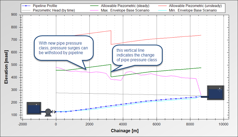
Here it is noted that, now, the Maximum Allowable Piezometric head for steady flow condition (pipe’s nominal pressure) covers much (almost all) of the Maximum Piezometric head for water hammer condition, only through the switching of pipe’s pressure class.
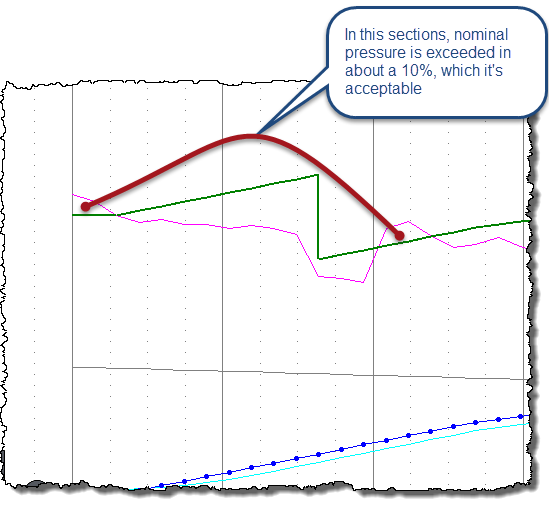
In any case, we also observe that short pipeline sections remain where the allowable envelope is exceeded by the water hammer one, but the Water Pipeline Design can be considered ended, as such exceedance is less than 10% of the pipe’s Nominal Pressure (lesser than the usual hydrostatic test pressure for water pipelines: 50% above its Nominal Pressure):
As we have seen, the Ariete’s possibilities to enhance the Water Pipeline Design and Analysis are many … Why are you waiting to turn it into your new engineering design tool?


