

Since versions 2.30 of CLOACAS, 2.30 of DREN-URBA, 1.10 of AQUEDUCTS, 3.50 of PLUMBER and 3.10 of DRAINS, we have included the possibility of loading as a background image, drawing files created with a graphic scale/real scale relationship different than one unit of drawing equal to one meter in real scale.
Remember that our programs, although they have the option of selecting between different units (of the international system and the English system), internally perform all the calculations based on units of the international system (meters, millimeters, kilos, etc.)
In this way, from the aforementioned versions released in March 2019, you will see that, when selecting the option Load at the Background Image panel from the DRAWING tab, once you have selected the corresponding (DWG/DXF) drawing file, the Units Selector dialog is shown:
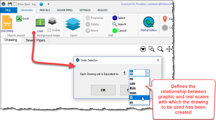
In it you can set the relationship between a drawing unit and the real distances in the drawing used.
With this information, in each program, the scale conversion will be carried out in such a way as to guarantee correspondence with the real lengths and areas of pipes and polygons, respectively, in the corresponding calculations.
In this regard, there are several points to highlight and that we consider should be taken into account when starting to use the programs:
1.- The scale selection can only be made in new project files
You can only make this conversion in files created from the version of each program referred to in the beginning of this article.
For project files created with previous versions, it will not be possible to execute scale changes.
2.- If you want to work with a background image, the first thing to do in a project is to load it
In most cases, you will want to load a background image that serves as a reference not only for the location or drawing of each project components, but also to take advantage of the features of the programs that allow it to perform the automatic assignment of lengths and areas required for the corresponding hydraulic calculations.
If so, the first thing you must do, once you have clicked the New Project option from the File page, is to Load the background image specifying the corresponding unit relation.
Therefore, the recommendation is that you use a background image drawing file that you will not modify late.
3.- Importing Objects from Microsoft EXCEL®
When you use the Excel option from the Objects Import panel in the Drawing tab, you will see that now the fields and properties selection dialog does not show the option to select the length unit for the object’s coordinates:
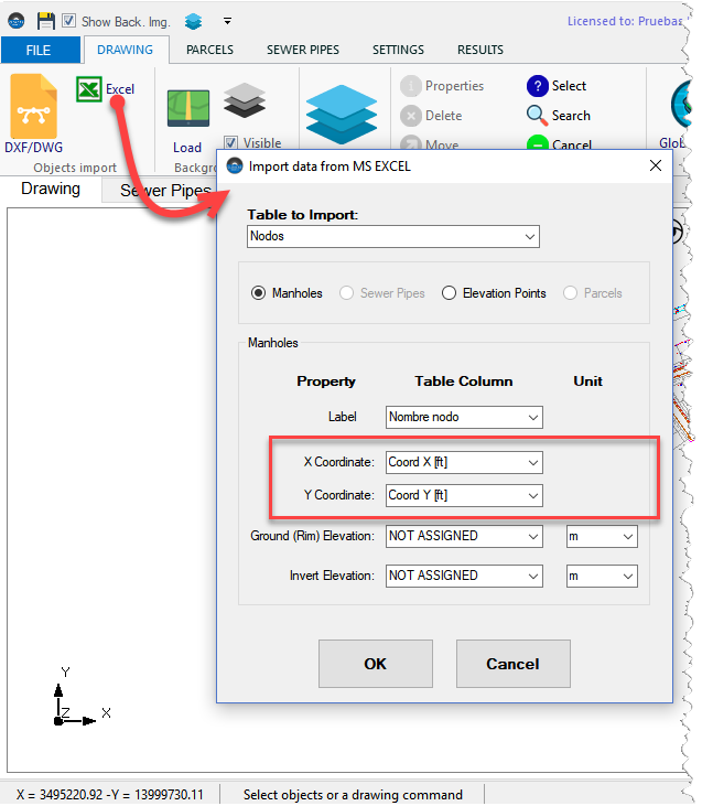
This is so because it is assumed that you have previously loaded, as a reference, a background image from which the scale of the drawing area has been defined.
When importing Nodes (having previously created the respective network), if you have not previously selected a background image, there will be the following warning:
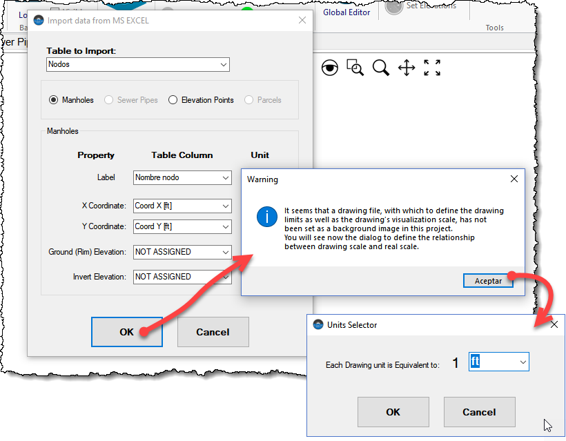
From there, by clicking the OK button, the well-known Units Selector will appear so that you can define the drawing scale here.
In this case, at the moment of importing, the programs will determine the limits (coordinates) of the surrounding rectangle of the imported objects, in order to internally perform the scale transformation.
For these last two components (Parcels and Elevation Points), if a background image has not been previously loaded or the Nodes and/or Pipes import option has not been used, an advertence message as the following will show:
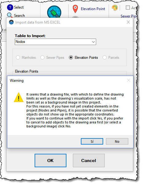
this message will notify you in relation to the possibility that the objects will not be drawn in the corresponding position and allow you to continue with the import (clicking Yes button) or cancel it (clicking No) to return to the drawing and load a background image.
4.- Importing Objects from Drawing Files
Analogous to the previous point, when you import graphic entities from a drawing file in order to be converted to objects in each program, and if you have not previously loaded a background image, the Units Selector will show:

in order to be able to define the necessary scale conversion.
Any difference in the drawing area extents of the drawing files you use may cause problems in the location of the imported objects.
Importing Elevation Points
Regarding the Elevation Points importing from objects contained in drawing files, you should bear in mind that the programs will consider that the unit of length of the elevations obtained corresponds to the one defined for the lengths in the SETTINGS Tab, Units panel of each program.
So, before importing, it is important to make sure that you have properly configured this unit so as not to have problems in the conversion, because internally the read values will be converted to meters based on the current unit.
You will also see in these new versions that having already created Elevation Points, the unit of length change in the SETTINGS tab will update the elevation to show its value in current units.
5.- Importing networks from EPANET (Only AQUEDUCTS)
When, from AQUEDUCTS, you use the option to import networks from EPANET .INP files, the scale is determined by the information that is defined for the corresponding file from the EPANET’S View Menu, submenu Dimensions:
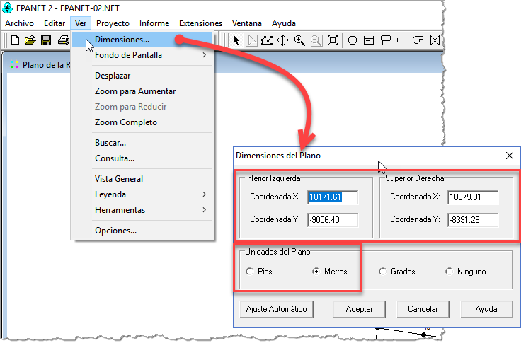
Based on the coordinates specified for the lower left corner and the units (feet or meters) specified there, the program will perform the necessary scale conversion.
6.- Changes in the Demand Polygons Editing Dialog (PARCELS Tab in AQUEDUCTS and CLOACAS)
In the most recent versions of AQUEDUCTS and CLOACAS, we have incorporated a selector for the area unit associated with the population densities for the “Density” type demand polygons:
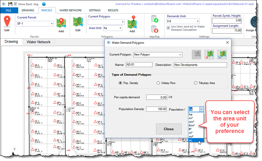
This way you can, at the moment of creating them, use the relation Number of inhabitants/area of your preference.
So, if you later modify the area unit without making the corresponding modification to the value of the number of inhabitants, it is very likely that the value stored by the program is not the adequate one. Keep this in mind when entering the population and area unit.
On the other hand, since we are in the issue of the water demands allocation using the tools in the PARCELS Tab of our programs, it is important to remember that the values of water demand established for the demand parcels that you have created in the drawing area will be updated as you make the unit change in the Settings panel of this tab:
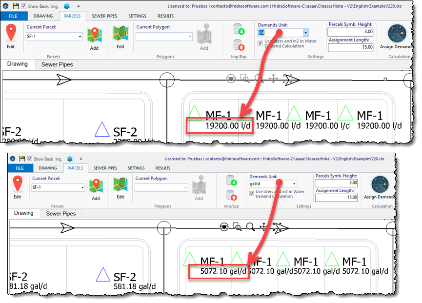
And keep in mind at the same time that the check box in this Settings panel allows you to define which will be the reference unit (international or English unit system) for the values of water demands contained in the water demand library of each program:
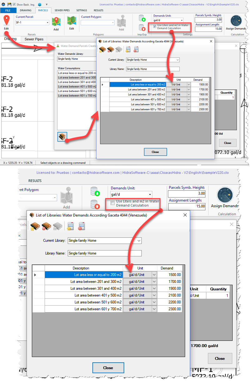
The recommendation in this case is that the first thing you do, before creating demand parcels, is to decide if you will work with liters per day and square meters (checkbox checked) or with gallons per day and square feet (checkbox unchecked) before you start using and/or create water demands in the project’s libraries.
If you have already created demand parcels based on water demands defined with one unit, the change to another one will generate inconsistencies in the resulting values.
One last recommendation: Use drawing files with only the information you need
Like any other computer program, ours depend on the memory of the computer in which they are installed.
Sometimes we have had clients and users who “complain” that the programs slow down when they load drawing files of more than 5 MB as a background image. There are even those who have uploaded 20 MB files, without expecting that the computer’s memory will be limited by this action!
This is something that can be easily controlled if you hide in the drawing file the layers of those objects that are not necessary to carry out your network’s layout and mapping work. Remember that you can do this from the Layer Manager of the background image of each program but it is more efficient if you do it previously from the drawing program of your preference.
Especially, in the case of drawing files with a large amount of text entities, the recommendation is that the layers that contain them be hidden to facilitate work within our programs.
Ideally, if you have a drawing program (such as AUTOCAD®), it would be ideal to “clean” the file you want to use as a background image in such a way that it contains only the layers and/or objects you require before loading it into any of our programs.