In this series of tutorials about using our DESAGÜES (DRAINS) software in the design of sanitary and pluvial drainage systems in buildings, we’ll review the aspects of creating, and editing as well as the designing itself of the horizontal branches system which, for the software´s purposes, we have called the network.
A sanitary Network in DESAGÜES is the group of horizontal branches (longitudinal slopes below 2%) or drains to which the sanitary fixtures’ traps are connected in the same building story and which discharges to a unique waste or soil stack.
Each Network in the software pretends to simulate the different sewage systems internal to the building and are located at each story. Thus, for those networks that are ‘typical’ (usually most of the networks’ layouts are repeated in more than two stories inside the building), it will be necessary to create only one and, to undertake the design of the waste stack, you must simply specify the number and type of networks served in each building’s level.
When creating a new project and after having set up diameters and sanitary fixtures tables for the project, the next step to be made in the sanitary drainage design in buildings with DESAGÜES is the creation of one or more networks. In this series of tutorials we will be using, as an example, a residential five story building (Ground Level plus 4 upper levels) which, in the Ground Level has 4 housing units, while levels 1 to 4 has two each.
The wastewater collection on the ground floor of the building will be made through two typical networks per each housing unit. Those networks will be discharging into one inspection chamber that is located near the building’s perimeter. In the next figure is shown the proposed collection system (per each housing unit):

Since the networks attending to the ground floor housings will be discharging into the building drains inspection chambers, it will not be necessary to create waste stacks (in the strict sense of the word) in the respective models into the software. But, to be able to create those networks in DESAGÜES, we´ll define the following ‘fictitious’ Stacks: Stke and Stke1 (see above figure) as their respective discharge points.
To collect wastewater from each housing unit in levels 1 to 4 we have proposed three networks, each affluent to a waste or soil Stack. The following figure shows the typical networks found on each of these building’s levels (per each housing unit):
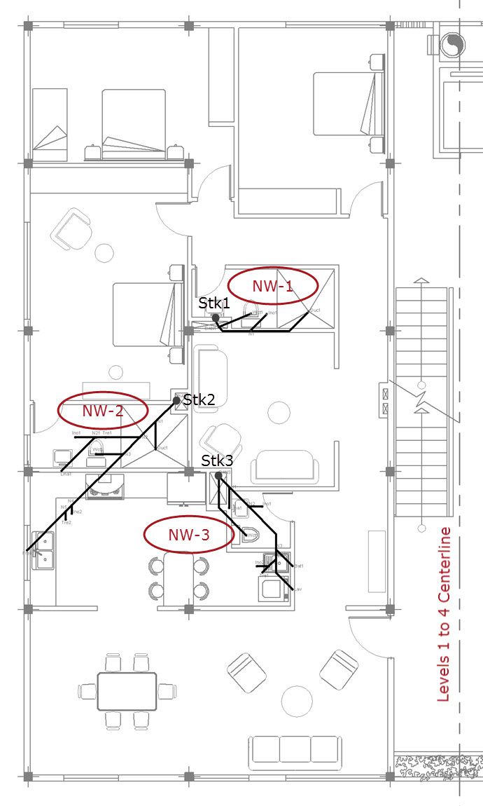
As you can see in the previous figures, we´ve used on the drawings the abbreviations proposed in this Tutorial, in order to identify the type of installed Sanitary Fixtures at the time of importing it from a DXF drawing file into the DESAGÜES’ project.
Thus, to model the entire sanitary drainage systems located inside this building, we´ll need to create only 5 distinct networks:
- Network NW-1: Serving the N° 1 bathroom in every housing unit at levels 1 to 4 and discharging into Soil Stack N°1 (Stk1 on above images). There will be in total eight of these networks in this building (2 housing units per level x 4 Levels).
- Network NW-2: Serves the N° 2 bathroom and kitchen’s fixtures in every housing unit in levels 1 to 4 and discharges into Soil Stack N°2 (Stk2 on above images). There will be also, in total, eight of these types of networks in this project
- Network NW-3: Serving the N° 3 Bathroom and the Laundry room of each housing unit at levels 1 to 4. Will discharge into soil Stack N°3 (Stk3). There are 8 networks in total.
- Network NW-GLe: Serves two bathrooms in each of the Ground Floor housing units. Discharges into the building´s sewers inspection chamber Node: Stke (fictitious Stack referred to previously). There are 4 throughout the building: 1 per housing unit x 4 housing units on the ground floor level.
- Network NW-GLe1: Captures waste water from sanitary fixtures in the laundry room and kitchen of each housing unit on the ground floor. Discharges into the building drain inspection chamber Node: Stke1. (There will also be 4 typical networks in the entire sanitary system).
Note that, although there is more than one typical sanitary network, in DESAGÜES it is only needed to create one for each typical network. Later, in the Soil stacks and building´s sewers design, we shall specify the quantities that each network is repeated to, finally, let the software to summarize the total Fixture Units in the sanitary drainage system of the entire building.
Creating the Sanitary Drainage Networks of the Building
To create the drainage Networks that represents the systems that we have defined in the previous section, we’ll create a new DESAGÜES project (Application’s Icon → New menu) and, will insure you have the Network tab active on the main window, click on New network button in Current Network panel. The Networks´ editor will be shown.
Here, we will set a name for the new network, a descriptive text (optional) and set the prefix that will be assigned to the nodes that the software automatically will be creating (the Prefix + sequential number will conform the nodes’ names):
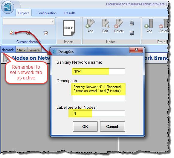
When you click onto the OK button, you will see that in the Nodes’ table the “Stack” node has been created. Remember that, for each sanitary network in DESAGÜES, a unique discharge point is required: this will be this Node. This node cannot be removed from the networks, although it is possible to edit its name or label.
Now you have two options for creating the sanitary drainage network components (Nodes and pipes or branches):
1. Create the network manually
This option is the recommended one if you are creating networks that have few horizontal branches, i.e., it is a small network.
In this case you must use the provided buttons to create nodes and drain branches and fill each of the fields in the respective dialogues. For nodes, an important aspect is to define, if applicable, the type and quantity of sanitary fixtures that discharges into it:
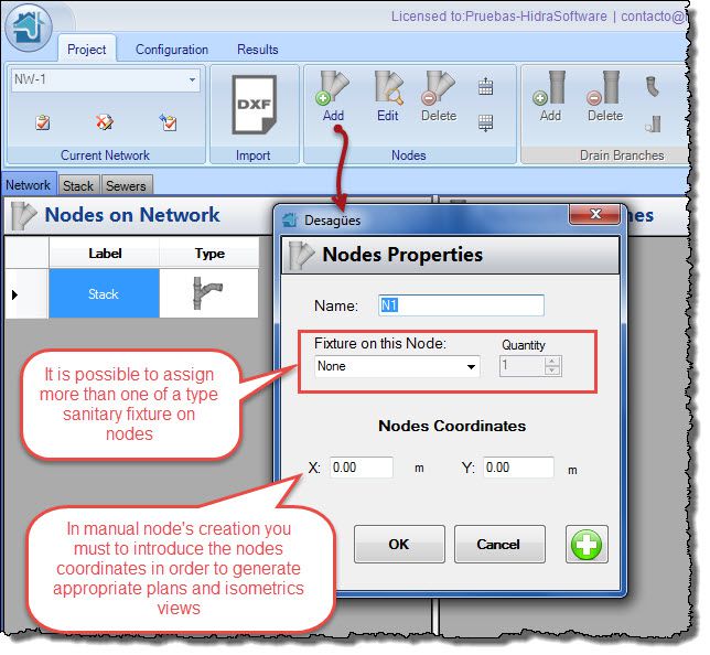
The values on fields in the ‘Nodes Coordinates’ section are necessary to perform the calculation of the pipe´s length (when user-defined length option is disabled on the pipe´s properties dialog), to obtain a network´s drawing plan and to generate isometrics views. If these values are not specified, you cannot take advantage of these software features.
It is necessary that you create first all of the network’s nodes before starting creating the horizontal branches, since the most important data, to specifying in them, is precisely its end and start nodes:
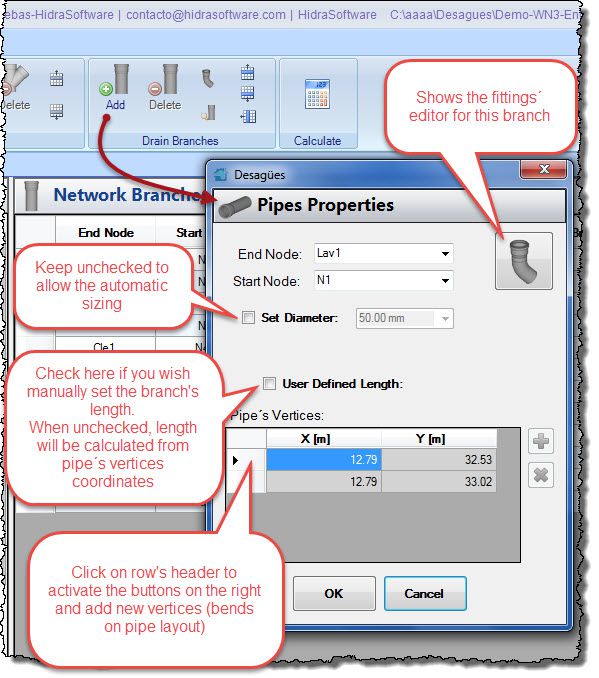
As you can see in the above figure, the drain branches are a most complex object in DESAGÜES, because they are really the components to be designed in the sanitary drainage system in the buildings.
In this dialog you will find, in addition to the fields to select the start (downstream) and end nodes (upstream) of the reach:
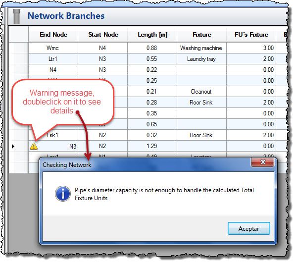
The option to set whether the program will select the diameter (‘Set Diameter’ option unchecked) from the values you specified in Project’s Pipes’ Diameter Manager – this is what we call de “design condition” (automatic pipes sizing)- or if, on the contrary, you will be whom fixes the diameter, overriding the automatic design (‘Set Diameter’ option checked) thus changing to the “revision condition” on the software. DESAGÜES will warn you, in such a case, if the diameter you’ve specified does not meet one of two criteria: diameter has not the capacity to convey the total calculated fixture units or diameter’s value is smaller than those of its affluent reaches:
If the pipe you are manually creating has changes in direction, it will be necessary to specify the required sanitary elbows (45° or 90°) and any other fittings you consider as necessary in the actual branch (the fittings required to build a cleanout, for example). You can do this through Fittings’ editor (click on button at the top right of the dialog):
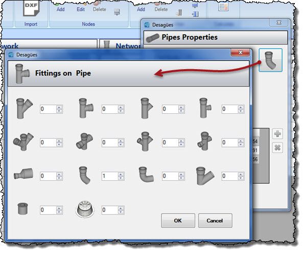
This ensures that DESAGÜES, when performing the calculation of drain reaches and fittings within the network, will account for what you have specified.
2. Create the sanitary drainage network from a drawing file
This option, we think, is the ideal in any case as it greatly simplifies the work of creation and supplying of the geometric data (lengths and fittings). In this tutorial you will see how easy it is to import dxf drawing files and convert them into a DESAGÜES’ project.
In our example case, as the networks have already drawn in a drawing file, we have chosen to create them through importing into DESAGÜES. (All dxfs files are included on the program’s installation folder so you can try by yourself).
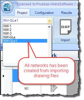
At this moment, regardless of how you have selected to build the networks, the view on DESAGÜES’S networks selector should be similar to the following:
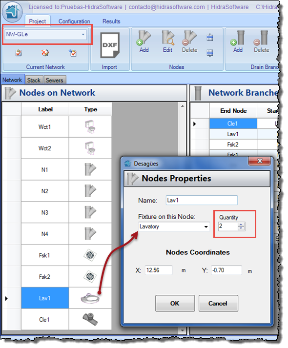
One aspect to consider in this example is the case of the Lavatories in the NW-GLe network:

In this case the Node ‘Lav1’ would be handling the fixture units of Two Lavatories, so it is necessary to edit the associated sanitary fixtures quantity on the Node´s editor dialog, (double click on respective row in the nodes´ table of this network):
Performing the Building´s Sanitary Networks Design
In this example, we have ensured that all branches in all sanitary drainage networks, have the ‘Set Diameter’ option unchecked (as we have previously explained), so as to allow DESAGÜES perform the automatic sizing (diameter) in order to convey the total calculated Fixture Units on each branch.
When clicking onto the Calculate button in the Project tab, a message dialog will appear indicating the calculation results in each of the project’s components. In this case, we´ll only take into account messages for the 5 existing networks, because it has not yet defined Stacks and/or building drains or sewers (nor sanitary nor pluvial):
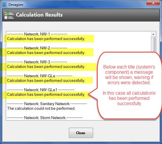
In case of detecting errors such as:
- Disconnected nodes in the drainage network (those to which no existing branch is connected).
- There is no exist, at least, one branch in the network whose start node be the respective waste Stack, and
- Portions of the network that are not connected to the waste Stack (this usually happens if you delete a branch without taking into account those in which it was discharging into).
will be presented, under the name of the component, the Message ‘The calculation could not be performed’ and right above it, will be shown the node’s or branch’s problem.
Now, for example, if we give a look to one of the network’s branches table, we can verify the sanitary drainage system design process (diameter selection) performed by DESAGÜES, which have involved two steps:
- Determining the required diameter as a function of Maximum allowable Fixtures Units specified on Project’s Pipes’ Diameters Manager.
- Establishing that, in any case, the diameter’s sizes increases with the flow’s direction (i.e. from the sanitary fixtures to the respective waste Stack). This involves verifying that the branches’ diameters are always equal or greater than the fixture’s trap minimum diameter defined on Project´s Fixture Manager.
In the next image we remark on the above referred points, based on the network NW-2’s branches table:
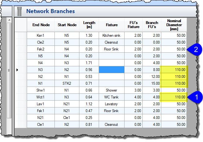
- WC’s trap diameter (110 mm) sets the downstream branches’ minimum diameter (yellow color).
- Remaining branches’ diameters will be calculated as a function of the maximum allowable connected fixture units (6 F.U. for ND 50 mm).
Thus, you see that the sanitary drainage network design process is rather simple, without too many revisions required from the user.
Now you can go to the Results tab and get the list of materials for each network. For example, the NW-GLe network will have the following result:
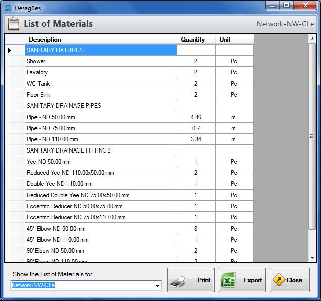
At this level, even though it will be available in the network’s list of the previous dialogue, it would not make sense to generate the list of materials for the entire project since we have not yet created Stacks, nor building drains, which will be used to totalize the materials at each network depending on the total number (per type) of them throughout the building (remember that we have created only one network for each type).
Finally, you can get the plans and isometrics of each network, annotated with calculated diameters as well as the lengths and fixtures´ names. The plan for Network NW-2 will be the following:
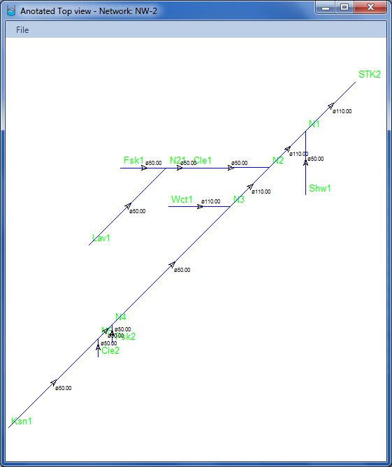
Those drawings (plan and isometrics) can be printed from the program or, to generate project drawings from your favorite drawing program, be exported in DXF format.
This tutorial’s Project file can be downloaded by clicking here.


