Even More Improvements in our Sanitary and Storm Sewer design Software (Update 2.20)


With update 2.20 of our programs for the design of sanitary and storm sewer networks, CLOACAS and DREN-URBA, respectively, we have introduced a series of improvements among which includes the possibility of exchanging information between them as well as with AQUEDUCTS, our offer for the design of water supply networks.

Thus, we want in this article and video to provide you with all the information to know what improvements they contain and how they can serve in your design work of these systems using our computational tools.

Changes in the Programs’ Interface and Addition of Interference Analysis with Other Networks or Pipes tools:

The first thing you will notice is that the visualization toolbar, available in the drawing area, now contains a new button, the Magnifying glass button, which allows you to enlarge small regions of the drawing without having to modify the current display scale:

Magnifying-button

Then, and here is where it has been almost necessary for a total redefinition of the properties structure of the software’s objects, you will see in the SEWERS tab the Analysis panel:

Analysis-panel-sewer-networks-design-software

The three buttons within this panel will allow you to export and import networks from CLOACAS, DREN-URBA and our newest software: “AQUEDUCTOS” (oriented, as you will suppose, to the design of potable water distribution networks) as well as to perform analysis of interferences or intersections between systems. This is a task of vital importance when designing pipe networks that will be buried since, especially in sanitary and storm sewer systems, the main function of the hydraulic design is the correct definition of the invert levels of the pipelines that generates the suitable slopes to comply with the normative and operational parameters.

Import and Export of Demand Parcel Data between CLOACAS and AQUEDUCTS

You will see in the PARCELS tab of CLOACAS and AQUEDUCTS, the “Import / Export” Panel:

Demand-parcels-import-export

The buttons in this panel are oriented to share, with the new program for the design of water distribution networks, the information of the demand parcels that you have in your project. We are looking here, assuming you are designing both systems: water distribution and sanitary sewer networks, to simplify the work by allowing the creation and assignment of demand parcels only once from one of the software, export the information to an XML file and, from the other software, you only have to import this information and save yourself the work of having to build the condition of distribution of demands in the area under study again.

Option to Generate the pipe sections longitudinal profile from the Elevation Points in the Project

You already know the great help offered by the use of the Elevation Point object to automatically define the terrain elevations of manholes or Nodes in your sewerage projects with our software.

Elevation-point-close-to-pipe

And while we assume that, in most designs and projects, the pipes are placed under existing or future road, where the longitudinal slope of the terrain is generally constant, following the suggestion of several licensees of our software, we have opted by adding the possibility of automatically generating, from the elevation points created in your work area, the terrain longitudinal profile of each pipe section.

This feature is simple to visualize: you will have pipe sections, like the one presented in the following figure:

where there are elevation points “close” to the pipeline. This situation would allow you to use their elevation values to give information to the program in the definition of the terrain’s longitudinal profile without having the users to do the introduction manually in the pipe’s properties dialog:

Defining-pipe-section-longitudinal-profile

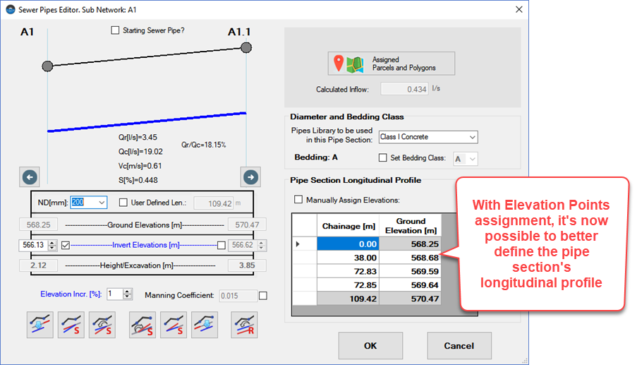
Of course, in any case, we have left a checkbox so that, if you wish, you can cancel this automatic assignment in the pipe section and manually enter, if necessary, the corresponding values.

Always bear in mind that the assignment distance or radius that you specify in the general settings of the project is what will be taken into account to define which elevation point(s) will be assigned.

The Demand Parcels Copy Tool (in CLOACAS and AQUEDUCTOS)

Another option requested with some frequency was the one to be able to copy and to paste the demand parcels inside the drawing area. This saves you a significant number of clicks, assuming that you are making their creation manually and not through importing information into a drawing file.

In this way you will see now that, when you select one or more demand parcels and right click the mouse, the Copy option appears in the context menu:

Copying-Demand-Parcels

From then on, the procedure is simple: move the cursor to the place where you want to create the new parcels, which will be copies of the first ones, and that’s it!

We leave below the video, outlining in detail the most important points from above.

We hope these new features in our software for the design of sanitary and storm sewers in urbanisms will be useful in your work:

Transcription

This minor update of our programs for sanitary and storm sewer design includes several features that we want to present you in this video.

You will now see that the visualization toolbar of the drawing area in each software includes the magnifying glass, with which you can see in detail certain areas of the plan drawing of the network.

Also, among the automatic elevations assignment tools using the Elevation Point object, we have included the possibility of defining the longitudinal profile in the pipe line alignment.

Let’s see how this is on the CLOACAS’ interface.

Remember that the definition of the method of elevations assignment is fixed in the general settings of the project.

Specifically, it is important that you be aware of the assignment radius, which in this case is set at 10 drawing units. Meters in this project.

Thus we are telling the software that, in the case of the pipe sections, any point that is at a perpendicular distance to it less than or equal to 10 meters, will be assigned to its specific terrain profile.

Let’s carry out the assignment and see what happens in the specific case of this pipe section, which has in its vicinity three elevation points.

So we click the elevations assignment button on the drawing tab.
You’ll see the successful assignment message to the manholes and,
when closing it,

The report of the assignment to the pipe sections will be shown.
For the section that we want to detail, 3 elevation points have been effectively assigned.

Let’s see their values in the pipe section’s properties.

In addition to its end point values, corresponding to the manholes’ terrain elevation, you will now see with their corresponding chainage, the three elevation points.

Here, in such a way that the assignment will be done automatically, you must keep this box unchecked.
And, if you want to assign values manually, just check it so as to allow you to modify them at your discretion.

The best thing here and, for sure, will interest you from the point of view of generating the drawings of your project, is that, in the respective longitudinal profiles, this modification will be reflected.

We’re going to show the A 1 sewer’s profile to prove it to you.

You see here that the terrain’s profile in the sewer pipe section has not constant slope but adapts to the topography of the terrain defined by the elevation points that you have created in your project.

What do you think? Isn’t it great?

Another useful feature in this update is the one that allows you to review and present in your longitudinal profiles the intersections with other pipes, belonging to other networks different from the one you are designing in the corresponding software.

You will see that in the SEWER tab of each program there is now a new group:

The Analysis group that you see here in CLOACAS.

But you will also find it in DREN-URBA as you will see now on its interface.

And, also, our new software AQUEDUCTS, contains this feature in the WATER NETWORK tab.

Here you can find the buttons that allow you to export the current network, so that it can be imported by the other software.

The idea is that, if for example, you are designing the sanitary sewer network, you will import the storm sewer network designed in DREN-URBA into CLOACAS.

Or, also, to import the water distribution network created in AQUEDUCTS.

Of course, in the opposite case, it is also possible to do this as we will see.

I am going to import the storm sewers network that we have already designed in DREN-URBA for this sector.
In this dialog you can have as many files as necessary.

Each of them with a different network. That is to say, with a different type of network: potable water system or storm water sewer.

In this case, I add the export file of the storm sewers network, generated in DREN-URBA, by clicking this button.

The info message confirms that it has been imported properly.

Note that the type of imported network is indicated here.

I activate this box to show, as a reference, the lines that define the network, in the software’s drawing area.

And, for the purposes of checking the separation between pipes, I specify here the minimum vertical distance
allowed between the top and bottom of the intersected pipes.

Note that the layout of the pipe sections in the storm sewer network are drawn in green, so that you can be guided at points where there is a cross between systems or networks.

Now, if we go to DREN-URBA, you will see that it is, indeed, the same layout that we have in the storm sewers project.

Let’s turn off some layers so you can see it better.

What remains is to perform the intersection analysis by clicking this button.

The table presents the required information to understand what level of conflict exists between the two compared systems.

You will see that it has information of the intersected pipe sections.

As well as the respective invert elevations at the intersection point.

It also tells you what the Top-bottom of pipes separation is and if the vertical separation condition, that we have specified in the network import dialog, is fulfilled.

Here you will see that there are not pipe sections that not only do not comply, but it seems that, in fact, intersect because they are practically at the same elevation.

Of course, the best way to see this is in the longitudinal profiles of the network. So let’s go to the Results tab.

And, first of all, let’s see something new in the profile settings dialog.

Here is the group of controls that will allow you to define the information that will be shown for the pipelines of the imported network that intersects with the one under study.

I am going to select the type of network as information, that is, to identify in the plans that the intersected pipeline is from the storm sewers system in this case.

The diameter of the pipe, entering the corresponding prefix.

And the same for the Top-bottom of pipes separation.

Of course you can specify the size of the text.

I’ll leave it at 1.5, the default in the software.

I close the dialog.

And, now, I show all the longitudinal profiles of this project.

There you have it. In the main sewer there are no crosses.

But in the secondary ones, you will see that the ellipse of the transversal pipe is shown, with the information that we have previously specified.

This is one of the cases in which we will have to make some modification in the invert levels of one of the pipe sections because, as we had foreseen, the pipes completely intersect. That is, there is no separation between their respective top and bottom.

You will see that, as part of the information that is generated for the intersected pipes, the chainage is also shown with respect to the start of the corresponding sewer profile.

In any case, you see that this new feature will allow you to make better designs, integrating all the sewer and aqueduct systems in such a way to reduce changes during construction and, of course, that you as a designer can foresee special works required to solve situations such as these.

Finally, we will show you quickly the same procedure and functions made from DREN-URBA.

Of course, in this case, the network to import will correspond to the sanitary sewer one for this sector, which I will quickly export from CLOACAS.

And which will be compared with the stormwater we are designing into DREN-URBA.

Then, from DREN-URBA, I select the file exported from CLOACAS.

Set the display and separation control conditions.

You will see that now it is the sanitary network, which we had in CLOACAS, the one that is presented in green as a reference.

And, when performing the intersections analysis, we will see the same table, with the only difference being that, in this case, the stormwater network is the one taken as reference, of course.

I will perform the configuration of the information to be shown on longitudinal profiles.

And let’s show them.

You see that, now, it is stated that the transversal pipeline is from the sanitary sewer system.

And, of course, here are the intersected pipes which we must adjust in our design to avoid the conflict.

So, as you have seen, both sewers design software and the water distribution networks one, share new features looking to exchanging information between them, just as it should be in any urban infrastructure project.

Therefore we hope that they are useful for your projects and we remain attentive, as always, to your comments.

Thanks for your attention.