Determining the design flows for sanitary sewer pipes depends on several factors such as regulatory and designer’s criteria as well as the available information, among others.
With the intention of offering greater flexibility in the Sanitary Sewer Networks design, CLOACAS (SEWERS) has included four possible methods for calculating the sewer pipes sections’ sanitary design inflow. In this tutorial, we develop the details of each of these methods and also give some considerations to take into account when creating a sewer network project in our software.
The selection of the method for wastewater design flow calculation in the software should be one of the first tasks to be performed (before starting the sewer network’s properties data entry) because, based on the chosen method, different data fields will be shown for the pipe sections in the Sewer Pipes Editor dialog.
Furthermore, it is necessary to emphasize that the selected method can be changed at any time (i.e., after the sanitary network has been built), but the design flow-related data, entered into the sewer pipe sections properties under the previously selected method, will be lost, which could represent a drawback for the analysis and design.
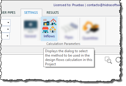
The sanitary sewer network project’s calculation method will be selected from the Wastewater Design Flow calculation methods dialog, accessed from the SETTINGS tab, Calculation Parameters panel, Inflows button:
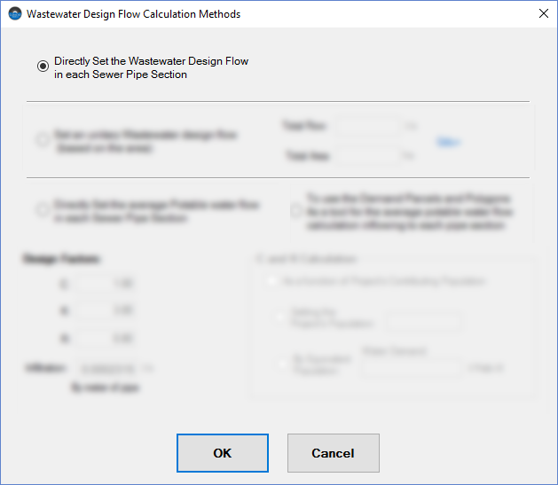
Here you will find the following options:
1 Directly set, for each sanitary sewer pipe, the corresponding Wastewater Design Flow.
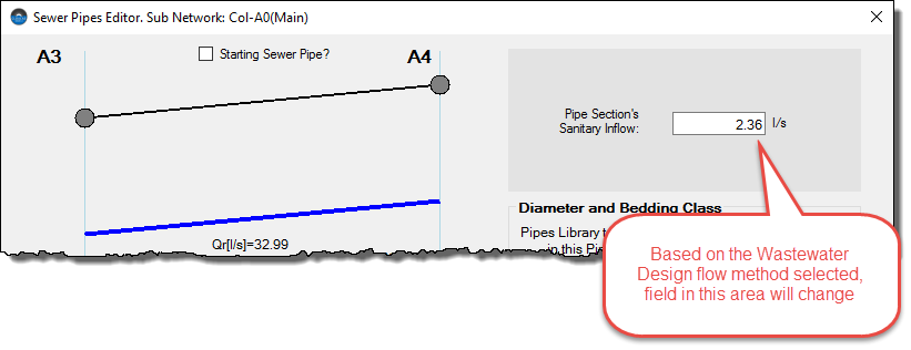
This is the simplest option in which it is a must to have the wastewater design flows calculated for each sewer pipe section within the sanitary network. When this option is enabled, the Sewer Pipes Editor dialog will show, in the upper right, a text box to allow the user to enter the respective value for the edited sewer pipe section:
2 Set a Unitary Wastewater Flow as a function of the area contributing to a particular sanitary sewer section.
When the sanitary sewer network’s total design flow, as well as the total contributing area, are known or, also, a Unitary Design Flow (l/s per hectare, for example), you can specify the respective values by activating this option:
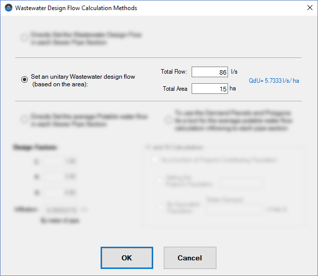
Now the Sewer Pipes Editor will ask, for each pipe section, the corresponding contributing area so the software can perform the respective wastewater flow calculation.
3 Directly set, for each sanitary sewer pipe, the corresponding Average Potable Water Design Flow.
If the available urban sector data is limited to each sewer pipe section’s average potable water inflow, this is the option to be chosen:
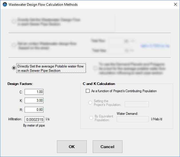
Here, the Sewer Pipes Editor will show a text box where the user must enter the affluent potable water design flow to each sewer pipe section within the sanitary network.
When this option is selected (as well as the next one that we will explain later), we see that at the bottom of the Wastewater Design Flow calculation methods dialog, several fields become enabled in order to specify some design factors:
- Security or Magnification Factor “C.” This parameter is intended to include, in the wastewater design flow calculations, aspects such as non-permitted inflows, such as connections from roof leaders and yard drains, among others.
- Harmon’s Peaking Factor “K.” The known factor, dependent on the design population, must be entered in this field.
- Return Coefficient “R.”
- Infiltration Flow “I.” To include the amount of water infiltrating through defective pipe, joints, fittings, and manhole walls, it is possible to enter here the corresponding value as a function of the sewer pipes’ length.
Counting all these factors, the Wastewater Design (Qd) will be calculated by the software with the following expression:

Where Qm, if the average potable water flow and Lcol, the sewer Pipe’s length
C and K factors Automatic Calculation Option
At the dialog’s bottom right area, we will see also enabled a check box with the text “As a function of Project’s Contributing Population”:
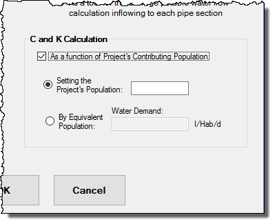
When this option is chosen, the software will offer the possibility that the C and K values are automatically calculated by the formulas:

In such a case, the user must enter the entire sanitary system’s design population in two available ways:
- Introducing the number of inhabitants directly.
- Using an Equivalent Population. If the design population is not known, it is possible to estimate it from a per capita water demand to be specified by the user in the field “Water Demand.” In this case, the software will determine the sewer network’s total average potable water flow (by summation of the average flows entered by the user, or allocated, at each pipe section) and will divide this total by the entered per capita water demand in order to get the number of inhabitants to be used in the aforementioned formulas. In this case, the values are not updated until the sanitary sewer network calculation has been performed.
4 Use Water Demand Parcels and Polygons.
This option is, perhaps, the most complex one, but can also provide more detail when determining the wastewater design flow in your sanitary sewer network’s project.
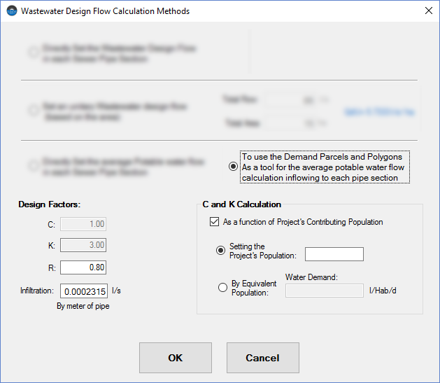
When this method is selected, we will see, after closing the dialog, that the PARCELS tab becomes enabled:

The idea here is to allow the user to define typical “Water Demand Parcels and Polygons,” which can represent the water demand in buildings like single-family homes as well as the water consumption based on the land uses within the urban sector.
The creation of these parcels depends on the Demand Parcels Creator and the Water Demands Libraries Manager dialogs, of which you will learn more if you see here.
This way, when this water demand objects are created and drawn into the sanitary sewer network’s area (at the software’s drawing area), the automatic allocation of them to the nearest sewer pipe section will be performed in order to determine the respective average potable water flow and, from here, to determine, as has been explained here, the corresponding wastewater design flow.
In this Tutorial, you will find more details about this feature.
We will see that, with this option active, the Sewer Pipes Editor dialog will show a button to present the table with the parcels and polygons allocated to the edited sewer pipe section:
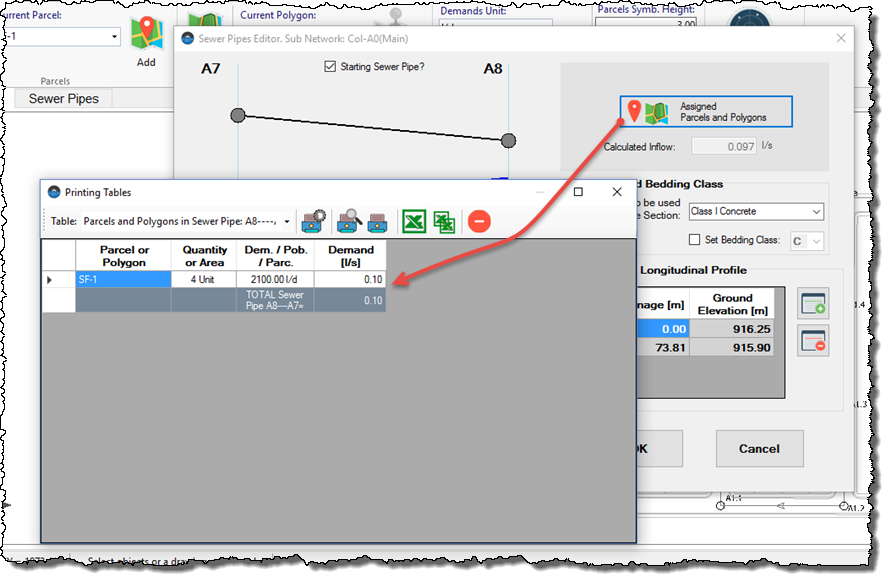
Note that the options to define, manually or automatically, the C, K, and R Design factors are also active, since what the user would be introducing under this method would be a potable water demand, which must be factored in, as we saw previously.


