In the second version of PLUMBER, launched in March 2014, we have included several features that some users have requested, and we have also added further improvements in its graphical user interface. In this article, let us roughly look at what’s new in our software for water supply systems design in buildings.
Graphical User Interface Improvements
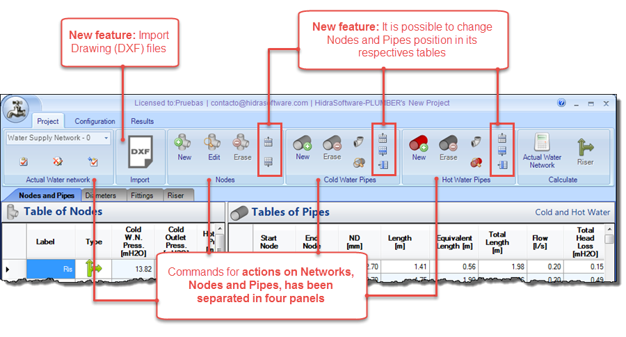
In order to better differentiate the available options for water network’s components creation, we have modified the panels’ structure on the Project tab, also including options that allow reordering of the rows on the nodes and pipes tables.
Thus, as highlighted in the next image, you will find in this new version the following features:

There you will also find a new Panel: the Import panel, with the ‘DXF’ button, which includes one of the new additions to the program, and that has also led to other changes in nodes and pipes data dialogs, as we shall see later.
Importing and converting entities in drawing files to the project’s components
Given that, in most cases, the design of water supply systems in buildings starts from the geometric design, specifically from sketching the water network layout in an architectonical plan which, in turn, is actually performed with drawing software (such as AUTOCAD® and others), we have included the option to import lines, polylines, circles, and texts from drawings in DXF format, and convert them to pipes and nodes that can be used for PLUMBER to perform the hydraulic analysis and design of the water plumbing system.
Although the DXF format is associated with the AUTOCAD® software, most drawing software has the option to export its drawings to this format. So all that is required is that the drawing software you use has this option available.
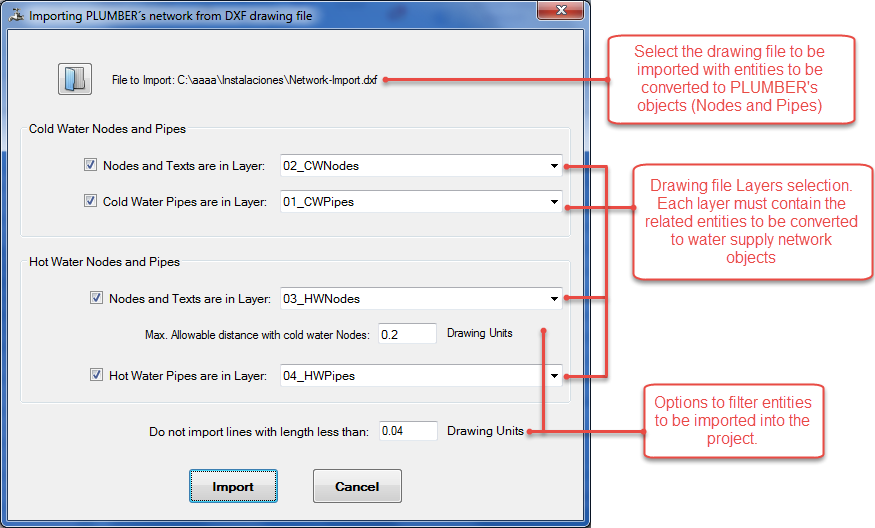
Thus, when using the DXF import option from the Project tab, you’ll see the Import dialog, which lets you to control in maximum detail the elements to import from a drawing file:

As shown in this tutorial, you only need to make sure the drawing file to import satisfies certain conditions, such as the separation of drawing entities in different layers, so that the import is 100% adjusted to the real geometrical design. You will see that with only minor changes in your drawing file, it is also possible that the importing process identifies the type of Sanitary Fixture associated to a node, thus minimizing the editing work within the software and, of course, reducing the possibility of data-entry errors from the user.
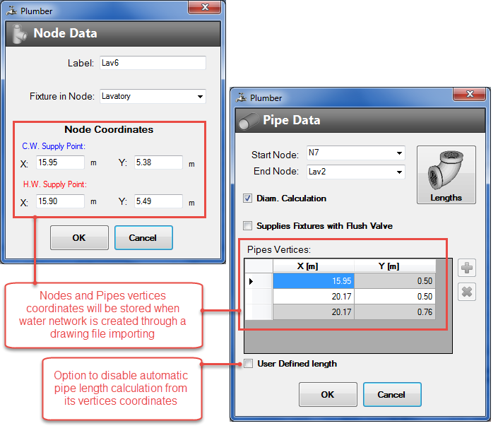
Going a step beyond the pure hydraulic design, incorporating the layout of the water supply network, you will see that dialogues for nodes and pipes editing incorporates now options to specify or modify the nodes and pipes vertices coordinates, in case their alignment is not straight:

Additionally, being that each pipe is now configured according to the coordinates of its vertices, the respective length will be, by default, automatically calculated in function to those values. Even so, has been included the User-defined length option, in order to override this automatic calculation in each pipe; thus, you´ll be able to specify the length value manually.
Note that these new coordinates’ fields will be with values different to zero if and only if you have made the importing from a drawing file, or if you’ve changed them manually.
For files created with the earlier version of PLUMBER (1.0) and for those projects that you have created without opting for the drawing files import option, these fields will be set to null.
Creating Plan and Isometric views of the Plumbing Water System
This is, for sure, the higher value addition to PLUMBER, since generating the plan and isometric views is part of the water supply system design in buildings, while serving as a tool for data visualization and analysis within the software.
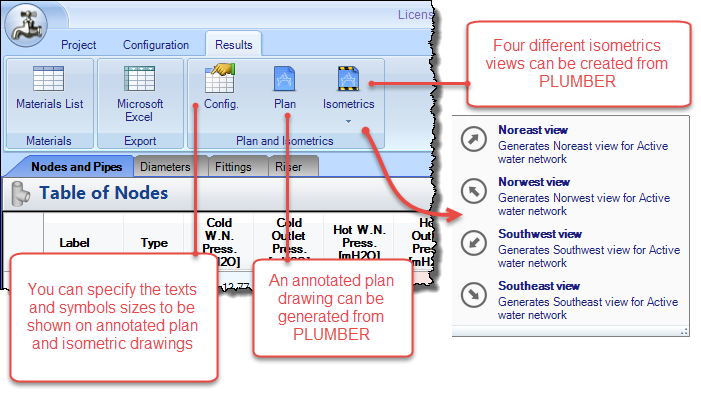
Then, in this new version, you will find in the Results tab a new panel with three options:

To create these Plan and Isometric views, it is necessary that, at least, the nodes in the project have values different from zero (0) in their X and Y coordinates fields.
Thus, you will be able to create the water supply network plan view, based on the nodes and pipes vertices coordinates and, as shown in the next image, it is possible to show the results of your design (diameters and lengths of each pipe) in the drawing:

In the case of the water plumbing Isometrics, you can choose from four different views, always taking as a reference the direction of the pipe that starts from the source point of the water network (the Plumbing Riser) and, as with the plan view, you can specify that the design results be shown in each pipe section:

From the dialog where the plan and isometric views are presented, you can choose to print them, or export them as an image or as a DXF format file in case you want to read it in your preferred drawing software.


