The last step in the design of sanitary drainage systems in buildings using DESAGÜES (DRAINS) is the sizing of the Building (house) Drain pipes. This is the drainage system´s component that receives the discharge from soil and waste stacks and, also, from other drainage pipes (usually horizontal branches on the buildings’ ground level) and conveys it to the Building sewer which begins outside the building walls.
In DESAGÜES, the building or house drains are formed by a series of straight sloping pipes interconnected by inspection chambers used, on one hand, to receive the Stacks’ and other drainage pipes discharges and, on the other, to undertake the changes of direction in the system´s plan layout on its path to the Building sewer.
The Fixture Units (F.U.) method for designing house drains is, if you will, a little more ‘complex’ than in the case of the horizontal branches network, as is required to define the maximum allowable F.U.s, for several diameters and for various pipe’s longitudinal slopes. You should have done this already, from the information you’ll find in your country´s standard codes regulations, in the Project´s Diameters´ Manager.
Continuing with our example of a residential building, for which we’ve been designing horizontal branches networks and Sanitary Stacks, the approach to the Sanitary building (house) Drain system is presented in the following image:

It is proposed that discharges of already designed sanitary stacks and horizontal branches on the ground floor´s housing units be concentrated on the inspection chamber IC1-W for sanitary components at the west wing of the building; on the east wing (remember that the building is symmetrical) the layout will be repeated, changing only Inspection Chamber’s name to IC1-E.
From the aforementioned Inspection Chambers (IC), the wastewater will be conveyed, using the required I.C.s, to the Building (house) Sewer. In this path, we have included the I.C.s: IC2-W (IC2-E for east side) and IC3-W (IC3-E), the first one needed to accomplish the direction’s change and the last to concentrate all the wastewaters of the building (West and East systems) at one point before ‘taking them out’ to the public network through ‘Dis’ Inspection chamber on the above figure.
Thus, in order to perform the building drains design, we must create in DESAGÜES (DRAINS) the nodes that will allow us to:
- Concentrate the wastewater from west side sanitary drainage components in IC1-W node, through the allocation on it of Stacks: Stk1, Stk2, Stk3 (only one of each) and Stke and Stke1 (two of each because the layout is repeated on the south house unit at ground floor).
- Similarly to the previous case will be done for the east wing of the building; the only difference is that the associated nodes will have the ‘E’ suffix, i.e.: East’s Stacks discharges will be concentrated in the IC1-E node.
To convey the wastewater to the aforementioned nodes (or inspection chambers) three sewer branches will be needed from Stacks Stk1, Stk2, Stk3, in addition to those required to interconnect to the remaining nodes.
But let´s begin with the building drains system construction:
Creating the Building Drains
As in the case of horizontal branches networks, building drains can be created manually, using the tools provided on the Nodes and Sewers panels in the Project tab (when Sewers tab is active). Also it is possible to import the objects from a dxf drawing file to create the building drain components. You´ll find the respective dxf file in the DESAGÜES installation folder (buildingdrains.dxf).
So, the first thing to do in the DESAGÜES project file containing networks and stacks created in the two previous parts in this series, is to activate the Sewers tab and make sure Sanitary Network is selected in the upper selector, inside the Current sewers network panel:
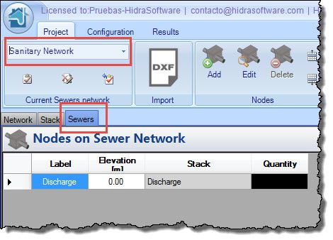
In this case you will see that the network is already created (i.e. it´s not possible to rename or add others to the project); this is so because the software assumes that there can only be a building drain network by type (Sanitary and Storm), each with a single discharge point (the point of connection to the public sewers network).
When Sewers tab is active note that already, in the nodes table, there exists a ‘Discharge’ Node. Like other components on DESAGÜES, this node is supposed to be the discharging point of the modeled system. You cannot delete it from the project because it is necessary to give consistency to the calculation and design.
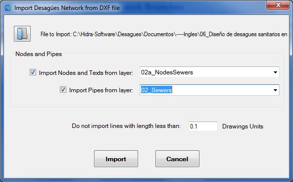
The importing process is already known for you. So, select appropriate layers as shown in the following image and click the Import button:
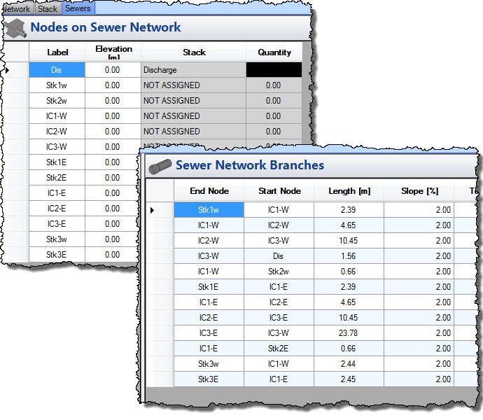
After closing the import results message, you´ll see the data on nodes and branches tables:
If you verify the imported data through visualizing its plan layout (Results tab, Plan and Isometric panel), you´ll see something like this:
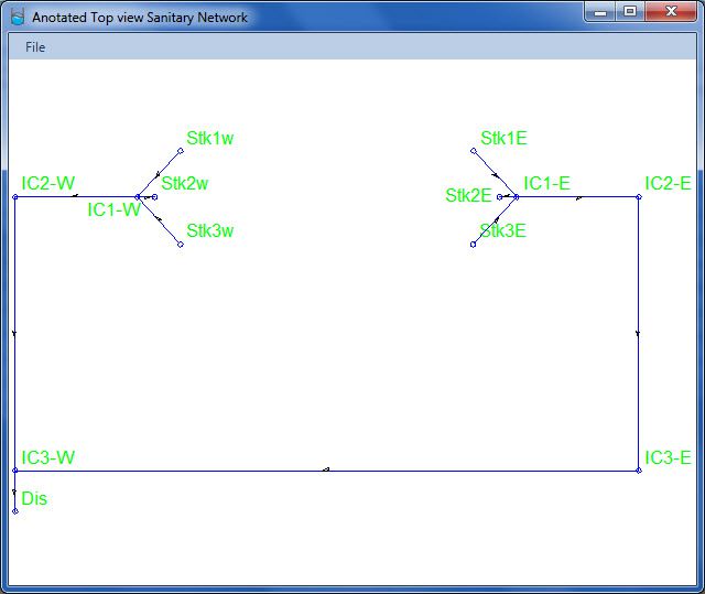
Everything is OK. Right?
Note that, in the nodes table, the rows for the Stack column have the words NOT ASSIGNED. This is to indicate that Stacks has not been assigned to those nodes (of course, not every node must have an assigned stack). Let’s add the Stacks as we have stated at the beginning of this tutorial. Consider, as an example, the allocation of Stk1 to Stk1w Node (Stack N° 1, west):

The same needs to be done for Stk1E node and for Stk2 and Stk3 in their positions East and West.
Association of Stk1, Stk2 and Stk3 (East and West) to their respective nodes, allows us to concentrate discharged wastewater on the IC1 node (W and E), and just rests to assign to it the ‘dummies stacks’ created to concentrate the discharge from the ground floor horizontal branches networks:
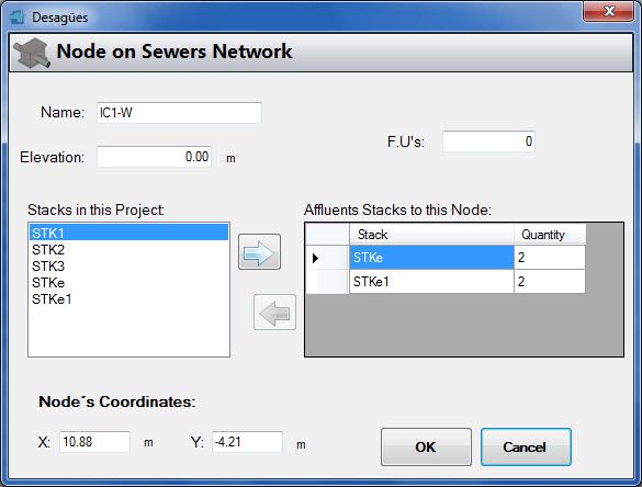
Finally, the nodes´ table must have the following view:
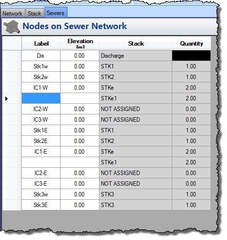
Performing the building drains network design
Before starting the calculation, it is important you choose the automatic design option to use on the General tab of the Pipes’ Diameters Manager.
Let´s see the resulting design when ‘Look for the lowest possible diameter’ is selected:

Note that, in order to obtain smaller diameters, some branches will have longitudinal slopes up to 4% while the maximum ND is 110 mm.
Let´s compare now with results when ‘Look for lowest possible slope’ is the automatic design selected option:
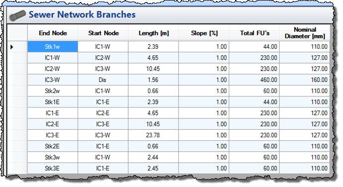
Now, longitudinal slopes does not exceed the 1% while the greater obtained diameter is 160 mm.
What is the best solution? On this theme, unfortunately, DESAGÜES cannot help. It is up to you!
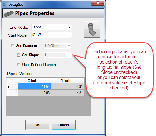
A new feature, presented on the building drains properties editor, is the field ‘Set Slope’:
Now (at last!) you can generate the Total List of Materials for the Project
After designing this last sanitary drainage system component, it is possible to generate, besides its respective list of materials, the total project´s materials list (including sanitary fixtures, horizontal branches, Stacks and building drains):

Finally, the Isometrics views for the building drains system can be generated from Results tab→Plan and Isometric panel:

And that’s it! The total Sanitary Drainage Design in Buildings has been performed easily with DESAGÜES (DRAINS). You can download the generated project file clicking here.


