As well as in our software PLUMBER, in DESAGÜES, the software for building drainage system design (sanitary and storm), we have incorporated the option of importing objects such as lines, circles, and texts from drawing files, in such a way to turn them into “hydraulic” objects such as pipes and nodes in the software. This minimizes user´s data entry errors and saves, in addition, a large amount of time in the project’s creation.
The idea behind this feature is that you can make the drainage network’s geometric design – plan layout – from your chosen drawing program (of course, following some conditions we will be giving in this tutorial), save it as a DXF format file, and then import it to DESAGÜES. Thus, assuming that the file import has been completely successful, you´ll need to just click on the Calculate button to get diameters, materials lists, and plan and isometric drawings with the required information (diameters, lengths and slopes) to generate your project´s documents. All this in just minutes!
Let us look in following sections for the aspects to be taken into account to set your drawing files, in order to be imported into DESAGÜES:
The DXF Drawing File Format
DXF format (Drawing Exchange Format)“ is a CAD data file format developed by Autodesk for enabling data interoperability between AutoCAD and other programs.” (Wikipedia).
We will develop this article based on this example of drainage network (which captures wastewater from sanitary fixtures on the same building´s story and discharges in a sanitary stack):

If you look at the drawing file’s components, you will find that following conditions have been fulfilled to achieve adequate importing to DESAGÜES (DRAINS):
1 Only Two Layers are required to contain objects that defines the network
It is necessary that a node’s name (a node must be created where a sanitary fixture discharges and where more than two pipes intersects) and the circle indicating its location are created or grouped in one layer. Likewise lines (or polylines) that identify branches or pipes must be in other layer. In our sample drawing these are as follows:
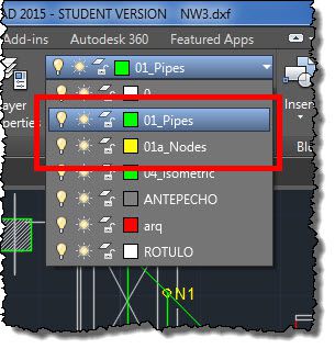
Layers can have any name. DESAGÜES’ import dialog lets you to select them from a list, as we shall see later.
2 Node’s names were created using Single Line Text
When importing, DESAGÜES will search only for single line text entities (command ‘Text’ in AUTOCAD®) closest to the node’s symbols (circles on the same node’s text layer) and will use its contents to define the node’s label in the project. In this process, one of the following situations may arise:
- No nearby text (in the same layer) is found, in which case the software will assign a name or label automatically for the node.
- A nearby text is found, verifying that the node’s name is unique (not repeated in the current project). If the name already exists, again, software will assign a new name automatically. If not repeated, the single line text contents will be used to set the name for the new node in this network project.
- Detects the closest text and verifies that the first three letters of its contents corresponds to one of the abbreviations shown in the following table. In this case the node will be created with the single line text contents as its name, but also will be assigned to it the corresponding sanitary fixture.
|
Sanitary Fixture |
Three first digits in Single line text contents |
|
Bathtub |
bth |
| Laundry tray | ltr |
| Bidet | bid |
| Shower | shw |
| Kitchen Sink | ksn |
| Drinking fountain | dfn |
| Dishwasher | dws |
| Lavatory | lav |
| Service Sink | ssn |
| Washing machine | wmc |
| Urinal (Valve) | uri |
| WC (Tank) | wct |
| WC (Valve) | wcv |
| Bathroom (Tank WC) | btk |
| Bathroom (Valve WC) | bvl |
| Floor Sink | fsk |
| Cleanout | cle |
| Stack | stk |
| Sewer´s Discharge Chamber | dis |
Pipes (or branches) have been created using line or polyline drawing entities
DESAGÜES will look for lines and polylines within the selected layer from the import dialog and will create the network´s pipes or branches. This is valid for both types of systems: sanitary and pluvial.
The only condition to be satisfied is that each line or polyline begins and ends in any of the circles defining the nodes’ locations. That is, if the plan layout of some of the pipes has changes in direction (bends where sanitary elbows will be necessary), you must use a polyline as we did to define the branch N2-N3 on our drawing file example:
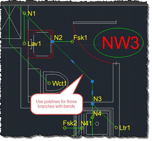
Even though, from the software, it’s possible to “reverse” the pipes’ start and end nodes to correspond them with flow direction (positive convention is: end-to-start node), it is recommended that the creation (drawing) of the lines and polylines entities in your drawing be done from the upstream to downstream node of each pipe’s branch. In our drawing example, for N2-N3 pipe, the vertex 1 of the polyline would be located on N3 (upstream node), the second vertex corresponds with the change in direction and the third one would be located on N2 (downstream node).
All Set! Let’s Import
As described in the previous section, the process of creating a drawing file that is consistent with DESAGÜES is quite simple. Now you’ll only have to export it in DXF format from your chosen drawing software and store it on your computer to start the importing procedure.
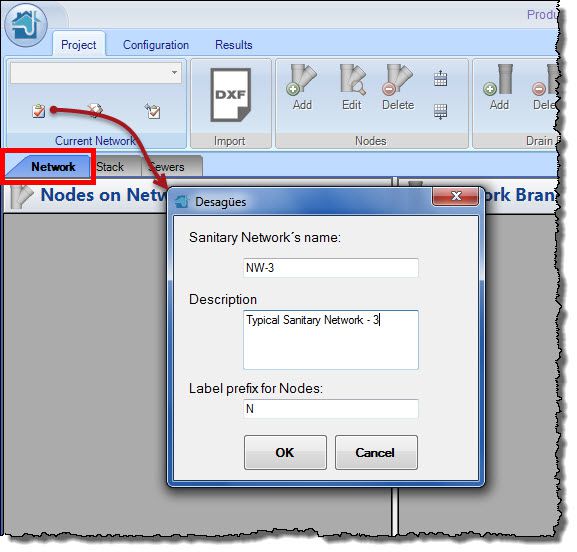
Since we are dealing in this example with a sanitary network, we´ll create a new one from a DESAGÜES’ blank project. So create a New Project from Main application menu, activate Network tab on main window (click on it), and click on create a New Network button on Current Network Panel:
With DESAGÜES, it is not only possible to create drains networks from a drawing file, but also networks of sanitary and storm building sewers. In the latter case, you must be located in the Sewers tab and select the applicable network type:
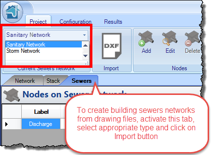
Once this is completed, the required following steps are similar to those described below.
Once a sanitary network is created, click DXF button on Import panel to access the Import dialog. Here you must perform the following sequence:
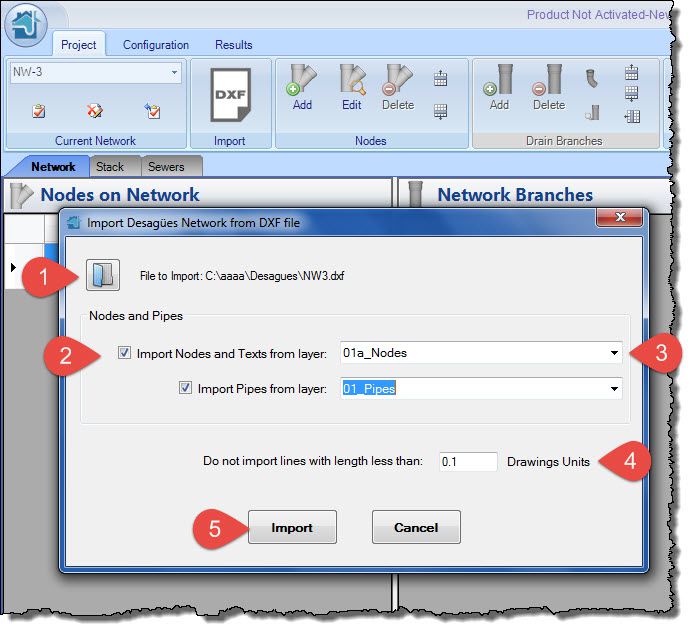
- Click button to access Open File dialog. Locate the path to your drawing in DXF format and click the Open button in that dialog. After reading the information, ‘File to import’ plus the path and selected file name text will be shown.
- Select (check) the check boxes ‘Import Nodes and Texts from layer’ and ‘Import Pipes from layer’. This will allow you to select the layers from the list on the right.
- Select the drawings layers that group the objects to be imported (and converted), as seen in above image.
- You can specify, as a filter, the minimum length (on drawings units) that lines and polylines to be imported must have. Thus will not be imported, if applicable, lines drawn by mistake.
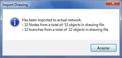
- Click on the Import button. If everything is OK, a message indicating how many objects have been imported and converted will be shown:
Additionally, when you close the previous window message, you’ll see that the nodes and pipes tables have been filled with data:
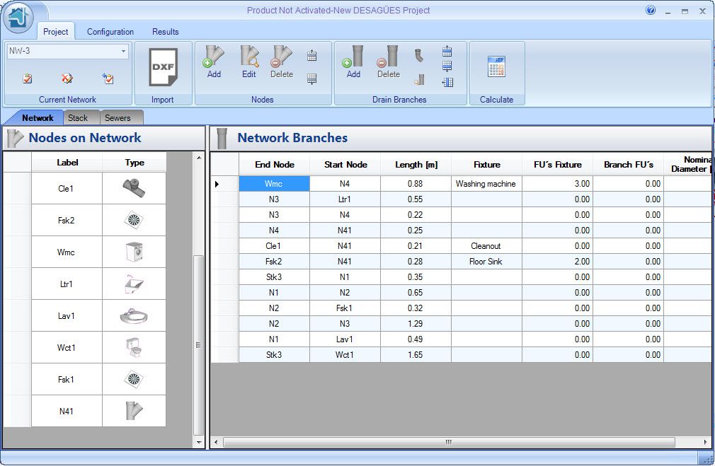
Of course, it is recommended to review that Sanitary Fixtures, nodes and pipes branches (end and start Nodes) have been properly created and are consistent with the original (drawing) sanitary network.
What have done for us the importing process?
To ensure the above verifications, i.e. that DESAGÜES (DRAINS) have ‘understood’ imported data, the next thing to do is go to the Results tab → Plan and Isometric panel and click on Plan button to show the annotated plan view:
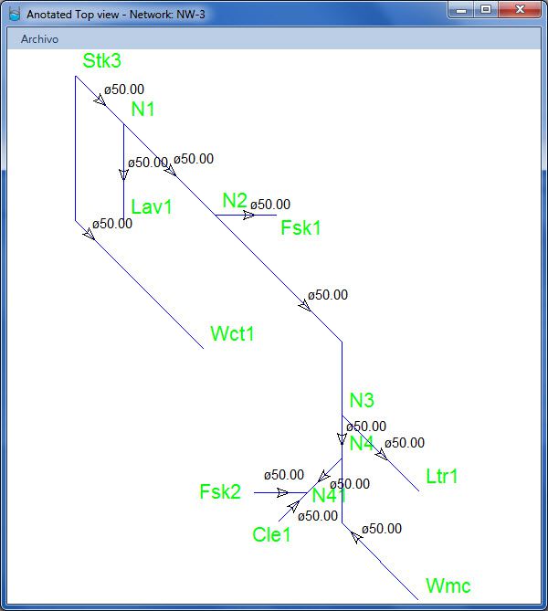
Do not panic if the directional arrows (as in the above figure) do not correspond to the real flow direction in the network. This happens by not complying, at the time of drawing, the recommendation that the first vertex of line (or polyline) must coincide with the end node (upstream) and the last one with the start node (downstream).
Once you click the Calculate button, the program would fix this, but you could also modify it manually using the available button on Project tab → Drain Branches panel:
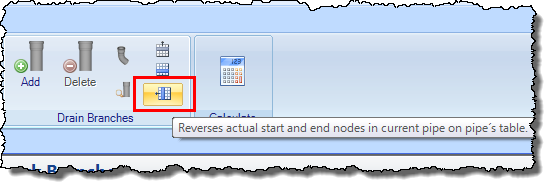
As shown in this example, except for the fact that some pipes have the inverted arrow, the network structure is exactly the same as the imported drawing. Let’s see what else DESAGÜES has done for us:
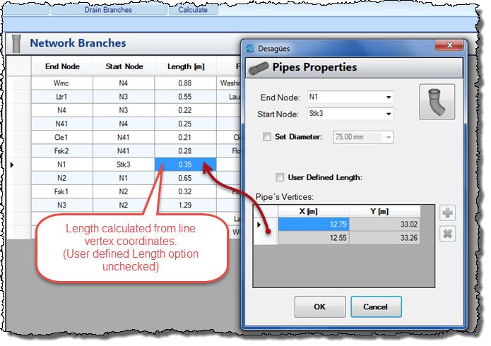
Pipes’ Length has been automatically assigned
You will see in the network branches table that the length field has the value corresponding to the length of the line that defines the branch and, if you access the pipes editor, double-clicking on any row, you’ll see that the User defined length option is disabled. This is the way to let the program automatically calculate the length based on the vertices coordinates of the pipe:
Pipes with changes of direction has now assigned the respective sanitary elbows
Clicking, in pipes´ properties dialog in the top right button, will show the Fittings editor for the selected pipe. For example, in N2-N3 pipe, see that the necessary 45° elbow has been automatically allocated:

As you can see, at this level additional editing is not required. You only have had to “check” or confirm that what has been created are the nodes and pipes that represent the sanitary network you are going to design with DESAGÜES.
The importing process from Drawing files is very easy. Isn’t it so?


