In the current version of our Sanitary Sewer Design Software: CLOACAS (SEWAGE), both the design and the longitudinal profiles creation approach is based on the premise that the user has previously defined the sub networks representing the various circuits or branches which make up the Sanitary Sewer Network.
In this tutorial you will learn how to define the various sewer sub networks, once the network has been created in any CLOACAS project. In the following image, the sanitary sewer network to subdivide is shown:
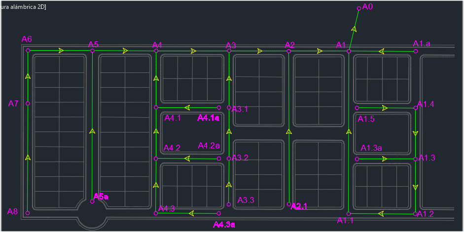
As you can see, names or labels have been assigned to manholes in order to maintain a reference to the sanitary sewer network’s discharge point (“A0” manhole) and according to the branch´s position, establishing, where possible, its order (primary, secondary, tertiary, etc.) through the sequence of numbers to the right of the letter “A.”
For example, the sewer pipe section A1.3.1 – A1.3, is the “A1.3” sub network, having a third order, because it is tributary to the “A1” sub network, one with a secondary order which is, at the same time, affluent to the sanitary system’s main sub network: the “A0.”
In the following table we list the sub networks in which the sanitary sewer network will be divided in this example, indicating assigned pipe sections to each one:
|
Sub network’s Name |
Conforming Pipe Sections (Upstream Manhole – Downstream Manhole) |
|
A0 |
A8 – A7 A7 – A6 A6 – A5 A5 – A4 A4 – A3 A3 – A2 A2 – A1 A1 – A0 |
|
A1 |
A1.5 – A1.4 A1.4 – A1.3 A1.3 – A1.2 A1.2 – A1.1 A1.1 – A1 |
|
A1.3 |
A1.3a – A1.3 |
|
A1.a |
A1.a – A1 |
|
A2 |
A2.1 – A2 |
|
A3 |
A3.3 – A3.2 A3.2 – A3.1 A3.1 – A3 |
|
A4 |
A4.3a – A4.3 A4.3 – A4.2 A4.2 – A4.1 A4.1 – A4 |
|
A4.1 |
A4.1a – A4.1 |
|
A4.2 |
A4.2a – A4.2 |
|
A5 |
A5a – A5 |
It is emphasized that the use of nomenclature in this example is not required for the proper operation of our Sanitary Sewer Design Software. The user can use the one that best suits his criterion, provided he is aware of the way the sanitary network’s sub networks are created, as detailed below.
Necessary Conditions for Sub Network Creation in a Sanitary Sewer Project
The creation of a sub network in CLOACAS is performed from the sub networks dialog (at the SEWER PIPES tab):
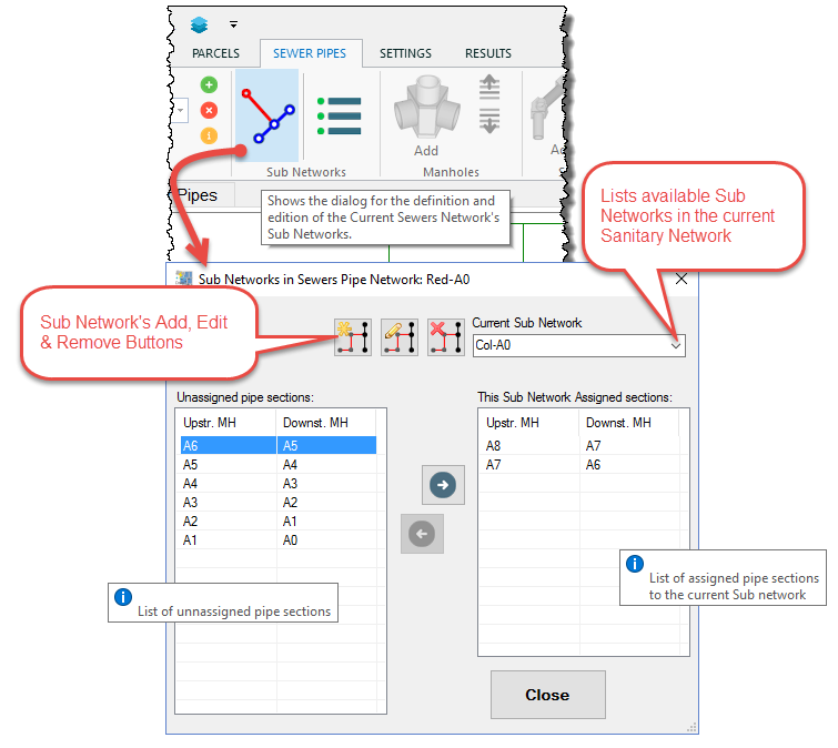
Thus, having pipe sections created in our sanitary sewer project, it is only necessary to consider the following conditions for assigning them to any sub network:
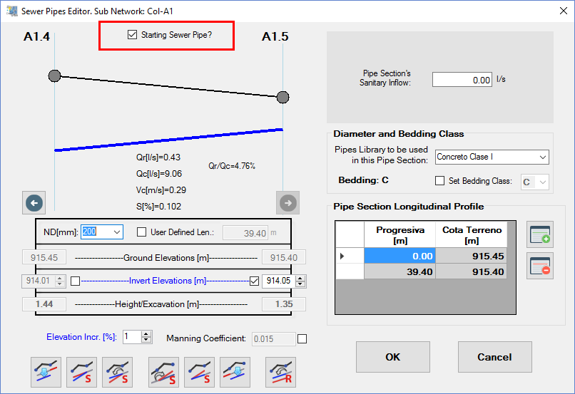
1 The first sewer pipe section in a sub network must be a “Starting Sewer Pipe”.
For the software’s purposes, a starting sewer pipe is one on which the upstream manhole does not receive sewage flow from any other pipe section of the sanitary sewer network. This pipe is where, in terms of the sub network’s development, the sewage flow collection begins.
Therefore, it is necessary, before accessing the sub networks dialog, to set as checked the property “Starting Sewer Pipe” in the respective sanitary pipe sections. To accomplish that, you must access the sewer pipes editor (by double-clicking the respective row in the sewer pipes table at the sewer pipes tab, or by selecting the pipe from the drawing area and right-clicking to access to the object’s menu, properties option):
In our sanitary sewer Network, the following pipe sections are Starting Sewer Pipes:
|
Sub Network Name |
Starting Pipe (Upstream Manhole – Downstream Manhole) |
|
A0 |
A8 – A7 |
|
A1 |
A1.5 – A1.4 |
|
A1.3 |
A1.3.a – A1.3 |
|
A1.a |
A1.a – A1 |
|
A2 |
A2.1 – A2 |
|
A3 |
A3.3 – A3.2 |
|
A4 |
A4.3a – A4.3 |
|
A4.1 |
A4.1a – A4.1 |
|
A4.2 |
A4.2a – A4.2 |
|
A5 |
A5a – A5 |
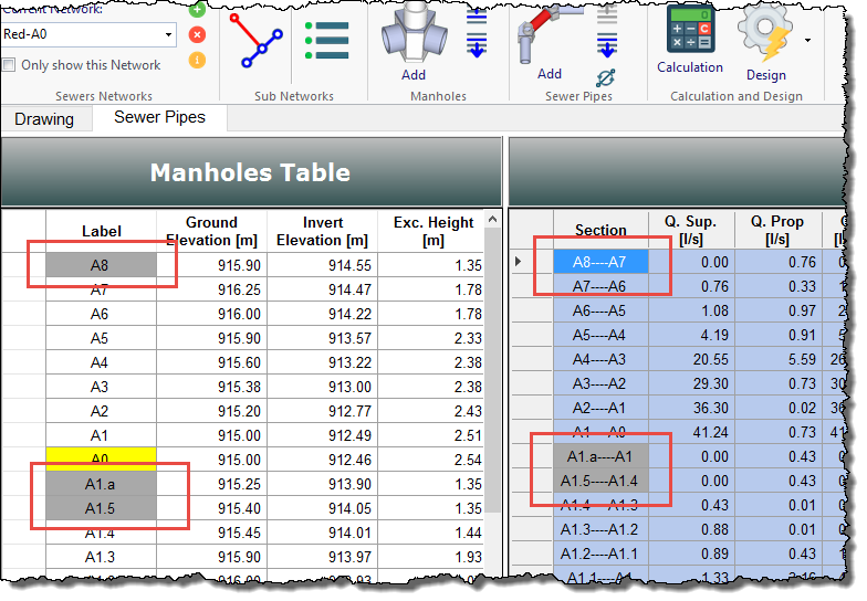
Once the “Starting Sewer Pipe” property has been set to true in any pipe section, you will see in the tables in the main window (SEWER PIPES tab) that the respective upstream manholes labels as well as the pipes sections will be colored in light gray, so as to warn you that these are the starting points at each sub network:
2 All sewer pipe sections at each sub network must be selected sequentially, from its starting sewer pipe to the most downstream one.
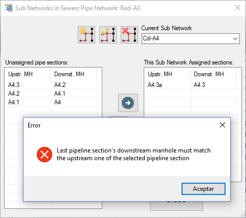
While this condition is a consequence of the above one and is also something, if you will, “natural,” it is important to note that the sub networks dialog will only admit, in any sub network’s creation, sewer pipe sections whose upstream manhole has the same label or name as the downstream manhole of its previously assigned pipe section.
For example, shown in the following image is the error message that popped up when we tried to add the pipe section A4.2-A4.1 to the “Col-A4” Sub Network. The program generates an error message because, since only the pipe section A4.3a-4.3 in the list of assigned sections is shown, it is expected that the following one be the A4.3-A4.2:
Creating and Adding Sewer Pipes Sections to a Sanitary Sub Network
Bearing in mind the previous considerations, we are ready to create the sub networks in our sanitary sewer network example.
From the sub networks dialog, select the Add button to show a text dialog to write the name of the sub network to create. In this case, we will create the “Col-A4” (see the table at the beginning of this tutorial):
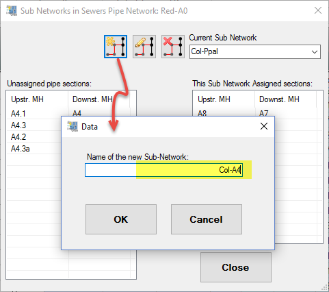
After entering the sub network’s name, click OK. You will see that it appears as selected in the current sub network list at the top right.
Now, let´s start selecting, from the unassigned pipe sections lists, those that will make up this sub network, given that the first one must be a starting sewer pipe. For sub network Col-A4, select the A4.3a-A4.3 pipe section and click on the right-arrow button:
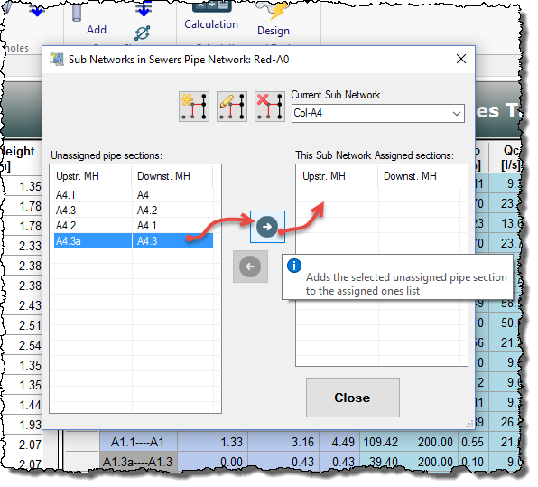
As a shortcut, you can also double-click on the selected section to add it to the list of assigned pipe sections without pressing the Add button.
When added, the selected section is removed from the unassigned list and we will see it now in the list at the right. Also notice that, if any, the program will set as selected, in the unassigned sections list, any pipe section whose upstream manhole’s name is similar to the downstream manhole’s name of the recently added pipe section. This eases the construction of the sub network.
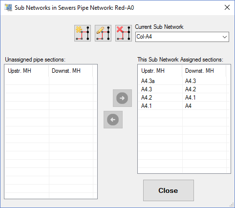
At the end, the “Col-A4” sub network will be defined as shown here:
Similarly, we´ll create the remaining nine sanitary sub networks for our example.
Grouping and Rearranging the Sanitary Sewer Network’s Pipe Sections
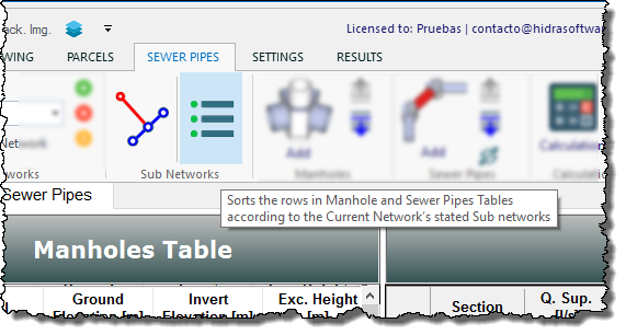
Finally, with the whole sanitary sewer network’s pipe sections grouped in sub networks, it is now possible, if the user deems appropriate, to arrange rows in the manholes and sewer pipes tables in CLOACAS’S Main Window based on the order that has been established for the sub networks.
To do this, you must select the Sort by Sub Networks option in the SEWER PIPES tab, Sub Networks panel:
Here we will see changes in the aforementioned tables:
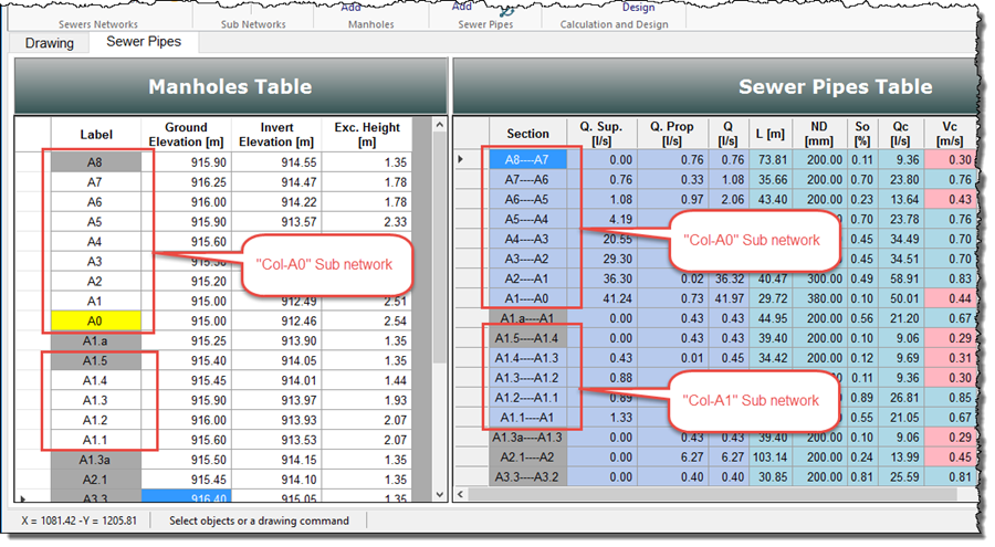
Thus, the results presentation and analysis is easiest.


